画像 1

IDAM
INA DRIVES & MECHATRONICS
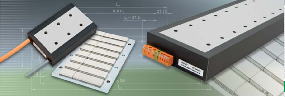
- LDDM
Linear Direct Drive Motors
- L1 Series
SCHAEFFLER GROUP

The Perfect Drive for Every Application
INA - Drives & Mechatronics GmbH & Co. oHG, a company of the Schaeffler Group, specializes in linear and rotary direct drives. These products are supplemented by directly driven positioning systems and related controllers and mechatronics assemblies.
The direct connection between motor and accelerated mass increases dynamic and static rigidity, reduces elasticity and therefore enables an extremely high level of positioning performance. Direct drives are non-wearing, as a result of which maintenance and operating costs can be reduced whilst simultaneously increasing availability. In the industries of machine tools and production machinery, automation, productronics/semicon, measuring technology and medical technology, teams at IDAM have been developing direct drives and complex drive systems since 1990.
The development of the direct drives and the positioning systems is efficiently supported by the integration of models and simulations.
IDAM employs a state-of-the-art quality management system. At IDAM, quality management is a dynamic process which is examined on a daily basis and is thus continuously improved. IDAM is certified according to standard DIN EN ISO 9001:2008.
In addition to standard products, IDAM also develops and produces customized drive solutions.
Due to the increasing demands in terms of dynamic performance, precision and cost reduction, direct drives are becoming increasingly more popular in modern machinery and equipment.


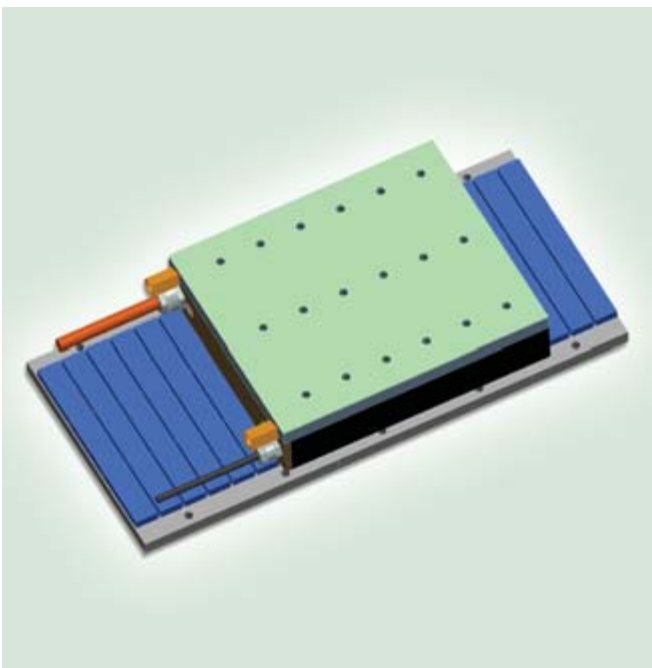
Specially developed software are used for the development and design of the motors, including tools for mechanical and thermal simulations. The results of these simulations are available to IDAM customers to help them optimize the assembling designs.
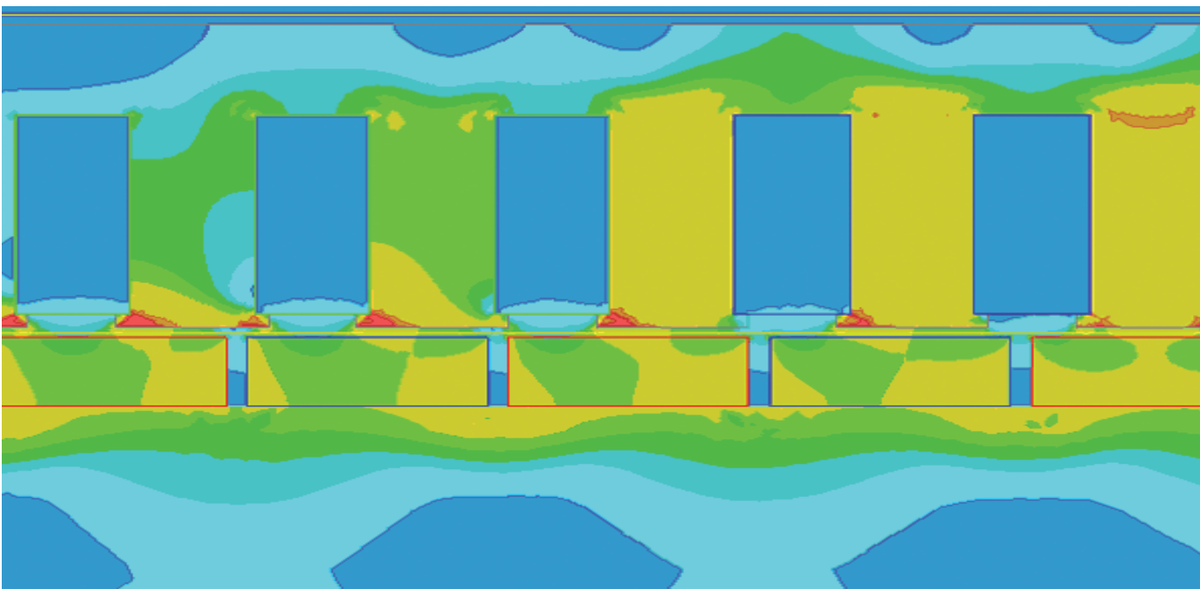
Detail of a FEM model
CAD model
2
Table of Contents
Technical Principles
Advantages of Linear Direct Drives 4
Overview of Linear Motor Series 6
General Motor Parameters - Efficiency Criteria 7
Force-Speed Characteristic...9
Force-Current Characteristic...10
Thermal Motor Protection 11
Electrical Connections...13
Commutation...14
Insulation Resistance 14
Dependency of Characteristic Data on the Supply Temperature of Cooling Medium...16
L1A Linear Motors 24
L1B Linear Motors 34
L1C Linear Motors 48
Technical Information and Consulting Services 68
IDAM Worldwide 69
Glossary...70
3
⚠️ Another layout reading thinks this page has no table. We still deliver what was extracted (withholding data is harder to audit than delivering it), but please look at this one on the original page yourself — per-cell confidence says whether a value has a second reading, not whether this is really a table.
この表はこのページから抽出されましたが、正確な位置を特定できなかったため、ここ(末尾)に表示しています。
⚠️ Only the vision reader saw this table — no other source overlaps it, so it may not be a real table.
| Technical Principles | |
|---|---|
| Advantages of Linear Direct Drives | 4 |
| Characteristics of Linear Motors | 5 |
| Overview of Linear Motor Series | 6 |
| General Motor Parameters - Efficiency Criteria | 7 |
| Winding Designs and Dependencies | 8 |
| Force-Speed Characteristic. | 9 |
| Force-Current Characteristic | 10 |
| Thermal Motor Protection | 11 |
| Electrical Connections. | 13 |
| Commutation. | 14 |
| Insulation Resistance | 14 |
| Cooling and Cooling Circuits | 15 |
| Dependency of Characteristic Data on the Supply Temperature of Cooling Medium. | 16 |
| Selection of Direct Drives for Linear Motions | 17 |
| Product Range | |
| L1 Linear Motors - Sizes | 20 |
| L1 Linear Motors - Features, Areas of Use, Applications, Advantages | 22 |
| L1A Linear Motors | 24 |
| L1B Linear Motors | 34 |
| L1C Linear Motors | 48 |
| General Information | |
| Check List for Your Enquiry | 66 |
| Technical Information and Consulting Services | 68 |
| IDAM Worldwide | 69 |
| Glossary. | 70 |
| At a Glance: Motor Forces of the L1 Series | 76 |
Advantages of Linear Direct Drives
Performance
1. No conversion of motion form
- The drive train is free of elasticity, backlash, friction and hysteresis caused by transmission or coupling elements.
2. Compact motor
- Thanks to the large feed force with relatively low accelerated mass, very high acceleration performance is achieved. The force can be used from speed 0 right up to the limit speed.
3. Direct measurement of position
- Thanks to direct position measurement and the rigid mechanical structure, positioning is performed dynamically and highly accurate.
Operating costs
1. No additional moving parts
- Assembly, adjustment and maintenance work for the drive assembly is reduced.
2. No wear in the drive train
- Even under high and frequently alternating loads the drive train is extremely durable.
- Machine downtimes drop as a result.
3. High availability
- In addition to increased service life and reduced wear, the robustness of the linear motors increases the system availability.
- Mechanical overload in the drive train does not cause damage as is the case with geared motors.
Design
1. Compact installation space
- The compact design results in drive modules with small space requirements.
2. Low number of components
- The mature design facilitates the integration of the motor parts in the overall machine concept.
- Fewer and more robust parts result in a low failure rate (high MTBF*).
3. Versatile design variants
- Facilitate an optimized integration of the motor parts into the overall machine design concept.
*MTBF: Mean Time Between Failures
4
1. No conversion of motion form
● The drive train is free of elasticity, backlash, friction and hysteresis caused by transmission or coupling elements.
2. Compact motor
● Thanks to the large feed force with relatively low accelerated mass, very high acceleration performance is achieved. The force can be used from speed 0 right up to the limit speed.
3. Direct measurement of position
● Thanks to direct position measurement and the rigid mechanical structure, positioning is performed dynamically and highly accurate. 1. No additional moving parts
● Assembly, adjustment and maintenance work for the drive assembly is reduced.
2. No wear in the drive train
● Even under high and frequently alternating loads the drive train is extremely durable.
● Machine downtimes drop as a result.
3. High availability
● In addition to increased service life and reduced wear, the robustness of the linear motors increases the system availability.
● Mechanical overload in the drive train does not cause damage as is the case with geared motors. 1. Compact installation space
● The compact design results in drive modules with small space requirements.
2. Low number of components
● The mature design facilitates the integration of the motor parts in the overall machine concept.
● Fewer and more robust parts result in a low failure rate (high MTBF*).
3. Versatile design variants
● Facilitate an optimized integration of the motor parts into the overall machine design concept.
Characteristics of Linear Motors
Direct drives enable a linear motion to be performed without motion converter or intermediate gears.
Linear motors comprise a primary part and, generally, a system of permanent magnets which is arranged opposite the primary part and is referred to as the secondary part. A distinction is made between slotted, slotless and ironless direct drives as well as stepper (synchronous reluctance hybrid motor) motors.
The motor develops a uniform and high typical force across a specific speed range. The force is determined by the active air gap surface between the primary and secondary part.
If a current is applied to the primary part, the electromagnetic field around the motor coils produces a force which acts on the secondary part and generates linear motion.
For a linear axis system a suitable guidance system is required in order to maintain the air gap between primary part and secondary part, as is a linear measuring system which detects the position of the motor.
Every series of motors comprises a selection of different lengths and widths in order to meet the different force and installation requirements and a range of installation and connection variants is also available.
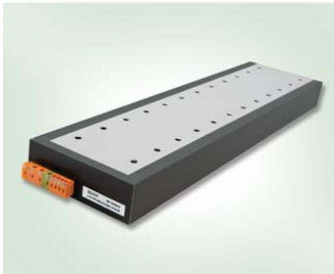
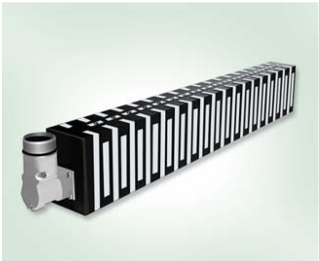
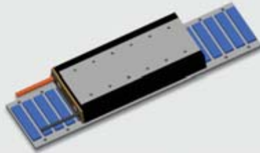
Type L1, primary part
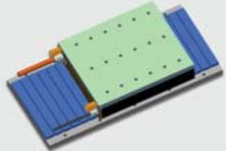
Type L2U, primary part
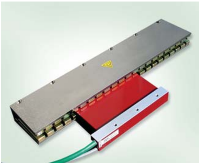
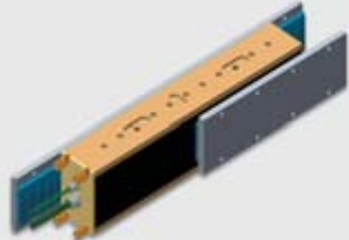
Type ULIM, primary and secondary part
5
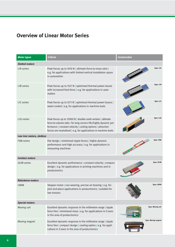
Overview of Linear Motor Series
| Motor types | Criteria | Construction |
|---|---|---|
| Slotted motors | ||
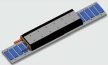
| L1A series | Peak forces up to 1010 N | ultimate force-to-mass ratio | e.g. for applications with limited vertical installation space in automation | Type: L1A |
| L1B series | Peak forces up to 1521 N | optimised thermal power losses with increased feed force | e.g. for applications in automation | Type: L1B |
| L1C series | Peak forces up to 5171 N | optimised thermal power losses | water-cooled | e.g. for applications in machine tools | Type: L1C |
| L2U series | Peak forces up to 12000 N | double-comb version | ultimate force-to-volume ratio | for long service life/highly dynamic performance | constant velocity | cooling options | attraction forces are neutralised | e.g. for applications in machine tools | Type: L2U |
| Low-iron motors, slotless | ||
| FSM series | Flat design | minimised ripple forces | highly dynamic performance and high accuracy | e.g. for applications in measuring machines | Type: FSM |
| Ironless motors | ||
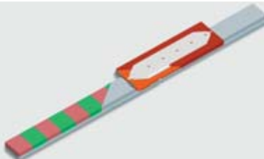
| ULIM series | Excellent dynamic performance | constant velocity | compact design | e.g. for applications in printing machines and in productronics | Type: ULIM |
| Reluctance motors | ||
| LRAM | Stepper motor | non-wearing, precise air bearing | e.g. for pick-and-place applications in productronics | suitable for low masses | Type: LRAM |
| Special motors | ||
| Moving coil | Excellent dynamic response in the millimetre range | ripple force free | minimised mass | e.g. for applications in Z-axes in the area of productronics | Type: Moving coil |
| Moving magnet | Excellent dynamic response in the millimetre range | ripple force free | compact design | cooling option | e.g. for applications in Z-axes in the area of productronics | Type: Moving magnet |
6
General Motor Parameters - Efficiency Criteria
Depending on motor size, the forces and the power losses incurred in the process (copper losses) are fixed for different operating points which are independent on the winding design. As linear motors also generate high forces at standstill without outputting any mechanical power, it is not meaningful to quote the efficiency factor here.
The motor constant kₘ can be used as a way of comparing the efficiency of motors. A high motor constant represents a more efficient conversion of
current into holding or feed force. It expresses the quadratic dependency of the generated power loss or heating on the load-independent current. This applies exactly to the linear dynamic range at standstill and at room temperature.
Pₗ = (F / kₘ)²
Pₗ: Power loss [W]
F: Force [N]
kₘ: Motor constant[N/√W]
As the motor warms up, its efficiency decreases as a result of an increase in the winding resistance (refer to the diagram).
With increasing speed, the power loss Pₗ are supplemented by frequency-dependent magnetic reversal losses and eddy current losses which are not covered by the motor constant kₘ, but which become relevant in the limit-speed range and must hence be taken into account. The motor constant kₘ relates to the linear region of the force-current characteristic.
The motor constant kₘ depends on the ohmic resistance and therefore on the winding temperature of a motor. In the motor data sheets, kₘ is specified for 25 °C. The diagram shows the dependency between referenced motor constant and temperature.
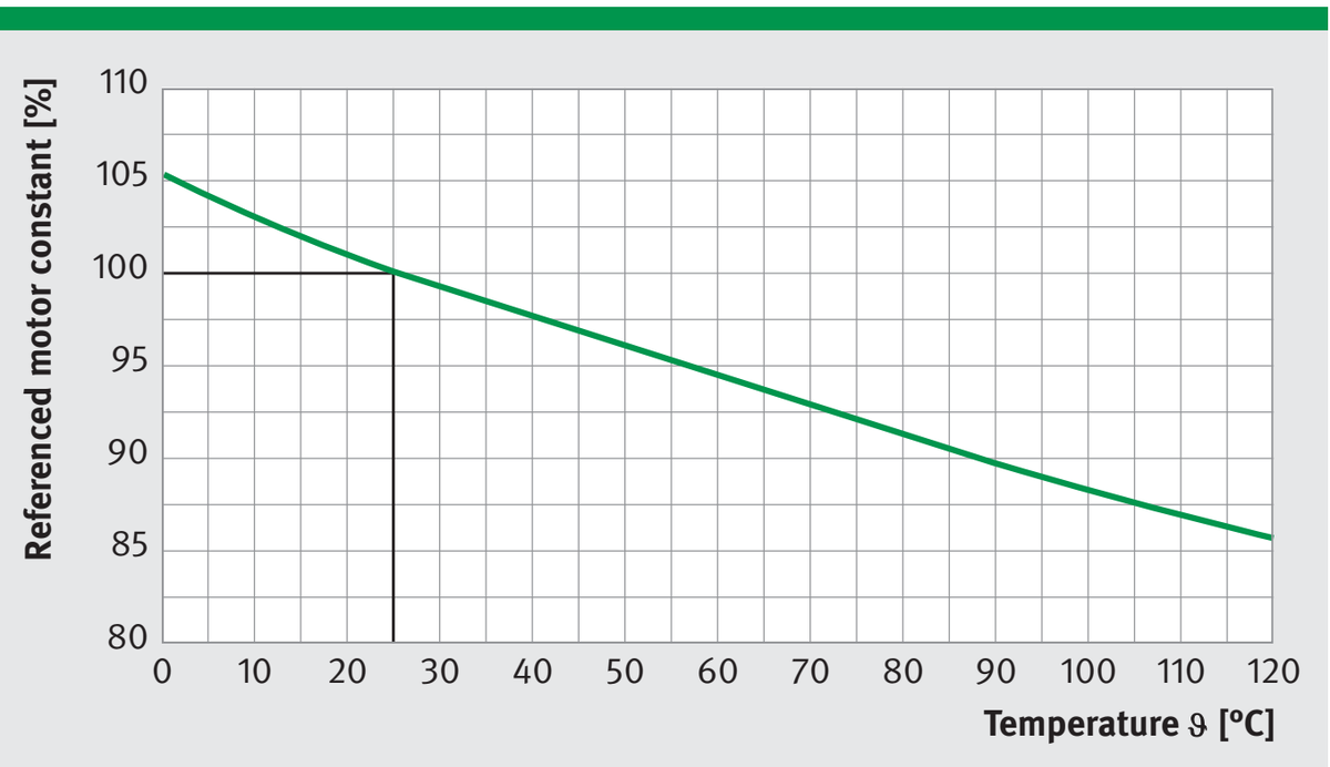
Motor constant vs. temperature
7
Winding Designs and Dependencies
The achievable limit speed of any linear motor depends to a large degree on the winding design and the link voltage (U_DCL). Internal voltage drops within the motor increase the voltage demand with increasing speed. At the specified limit speeds, the voltage demand with field-oriented control corresponds to the link voltage of the servo converter. After this point the speed decreases quickly.
The higher the link voltage and the smaller the winding-related voltage constants (kᵤ), the higher the achievable limit speeds will be. Due to the correlation between voltage constants and force constants, the current demand increases with higher speeds at the same forces.
For the winding data, a standard winding WM was predefined for each motor size for medium dynamic requirements
(winding variants WL and WH for lower and higher dynamic requirements respectively are available on request). At lower link voltages the limit speed is reduced almost proportionally. The force-current characteristic describes the force at various operating points. The force-speed characteristic presents the relationship between force and speed at different operating points.
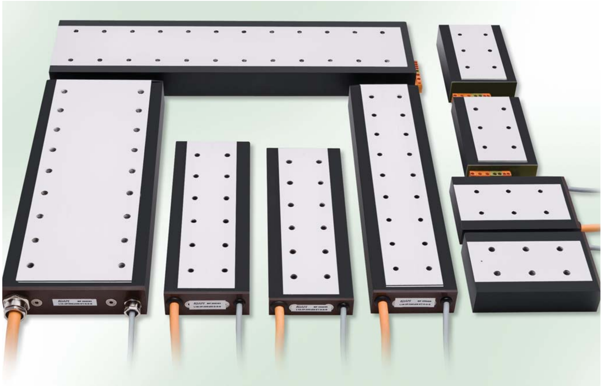
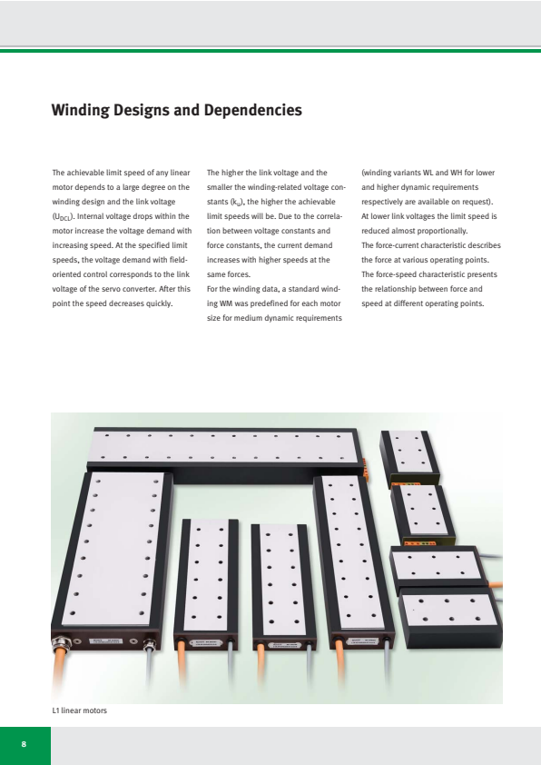
L1 linear motors
8
Force-Speed Characteristic
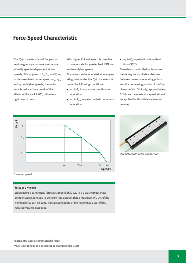
The F(v) characteristics of the permanent magnet synchronous motors are virtually speed-independent at low speeds. This applies to Fp, Fcw and Fc up to the associated corner speeds vlp, vlcw and vlc. At higher speeds, the motor force is reduced as a result of the effects of the back EMF*, ultimately right down to zero.
With higher link voltages it is possible to compensate for greater back EMF and achieve higher speeds.
The motor can be operated at any operating point under the F(v) characteristic under the following conditions:
- up to Fc in non cooled continuous operation
- up to Fcw in water cooled continuous operation
- up to Fp in periodic intermittent duty (S3**).
Closed-loop controlled motor movements require a suitable distance between potential operating points and the decreasing portion of the F(v) characteristic. Typically, approximately 0.2 times the maximum speed should be applied for this distance (control reserve).
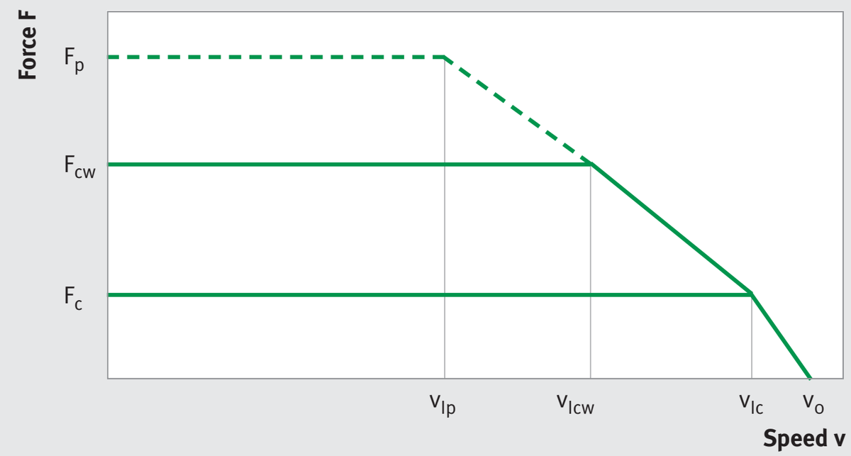
Force vs. speed
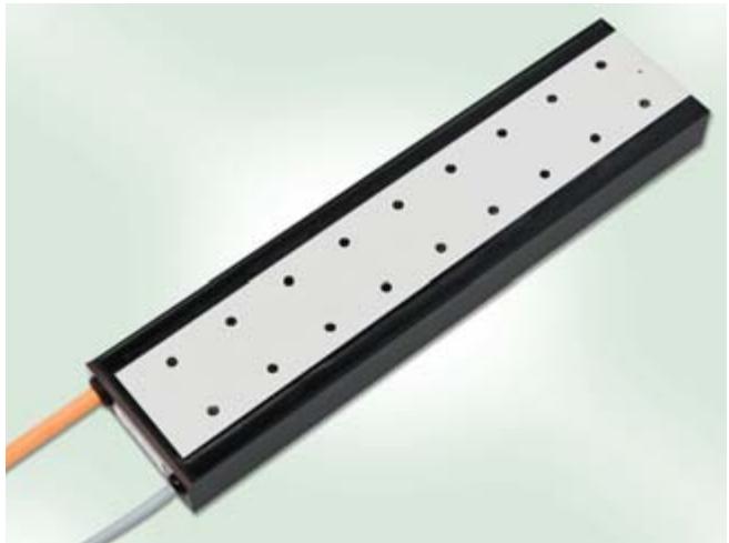
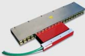
L1A motor with cable connection
Force at v = 0 m/s
When using a continuous force at standstill (Fs), e.g. in a Z-axis without mass compensation, it needs to be taken into account that a maximum of 70% of the nominal force can be used. Partial overloading of the motor may occur if this reduced value is exceeded.
*Back EMF: Back electromagnetic force
**S3: Operating mode according to standard VDE 0530
9
Force-Current Characteristic
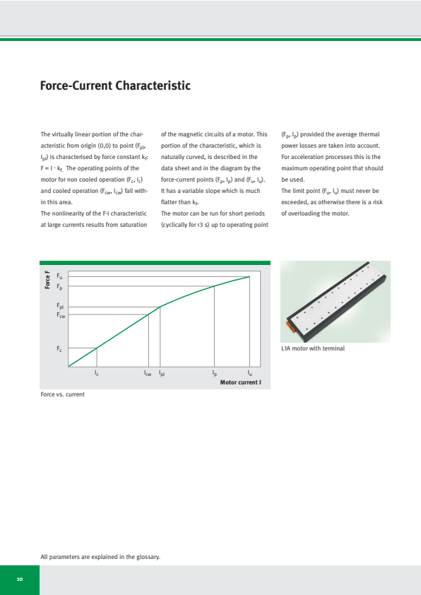
The virtually linear portion of the characteristic from origin (0,0) to point (F_pl, I_pl) is characterised by force constant k_f: F = I · k_f. The operating points of the motor for non cooled operation (F_c, I_c) and cooled operation (F_cw, I_cw) fall within this area.
The nonlinearity of the F-I characteristic at large currents results from saturation
of the magnetic circuits of a motor. This portion of the characteristic, which is naturally curved, is described in the data sheet and in the diagram by the force-current points (Fₚ, Iₚ) and (Fᵤ, Iᵤ). It has a variable slope which is much flatter than k_f.
The motor can be run for short periods (cyclically for <3 s) up to operating point
(Fₚ, Iₚ) provided the average thermal power losses are taken into account. For acceleration processes this is the maximum operating point that should be used.
The limit point (Fᵤ, Iᵤ) must never be exceeded, as otherwise there is a risk of overloading the motor.
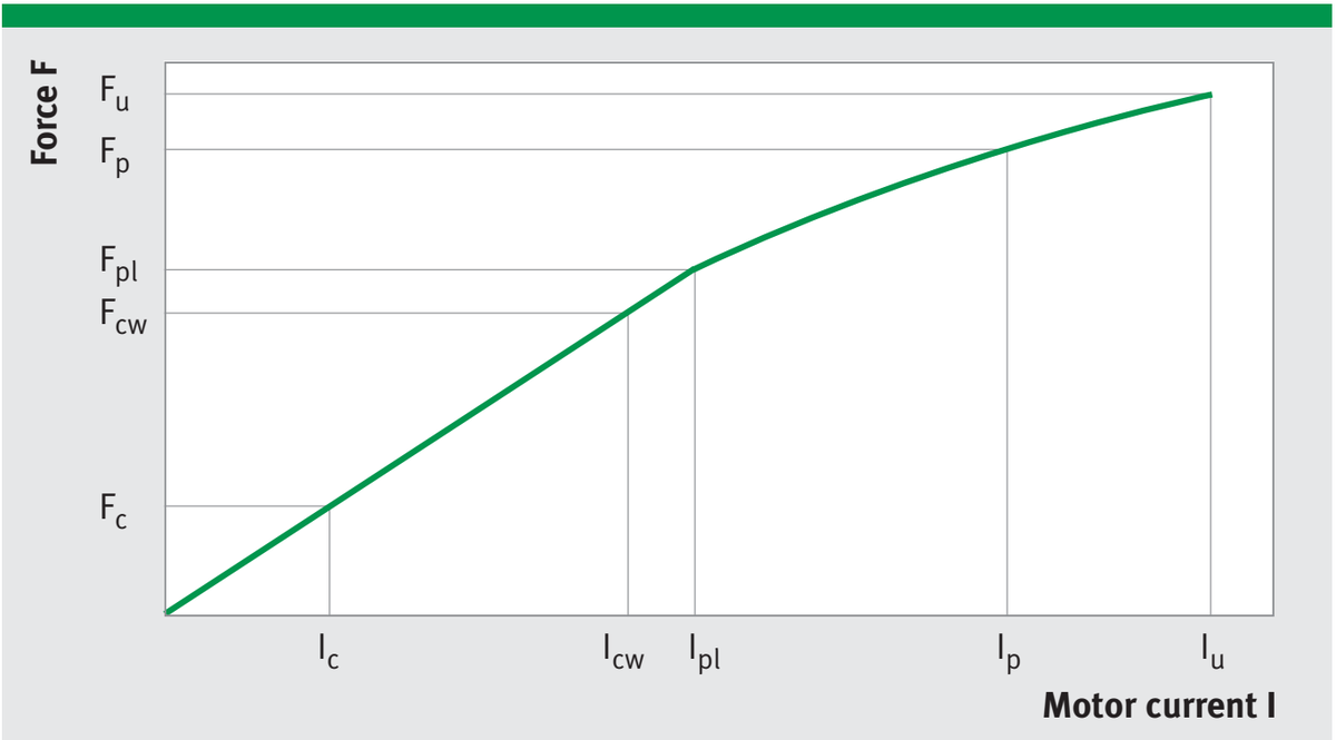
Force vs. current
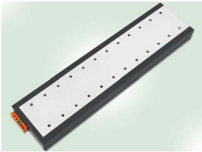
L1A motor with terminal
All parameters are explained in the glossary.
10
Thermal Motor Protection
Monitoring circuit I
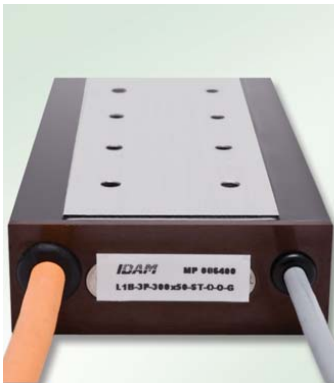
L1B motor with cable connection
Direct drives are often being operated at their thermal performance limits. In addition, unforeseen overloads can occur during operation which result in an additional current load in excess of the permissible nominal current. For this reason, the servo controllers for motors should generally have an overload protection in order to control the motor current. Here, the effective value (root mean square) of the motor current must only be allowed to exceed the permissible nominal current of the motor for a short time. This type of indirect temperature monitoring is very quick and reliable.
IDAM motors are equipped with temperature sensors (PTC and KTY) which should be used for thermal motor protection.
Monitoring circuit I
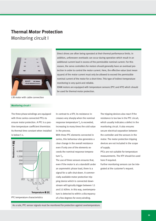
The three phase-windings are equipped with three series-connected PTCs to ensure motor protection. A PTC is a positive temperature coefficient thermistor. Its thermal time constant when installed is below 5 s.
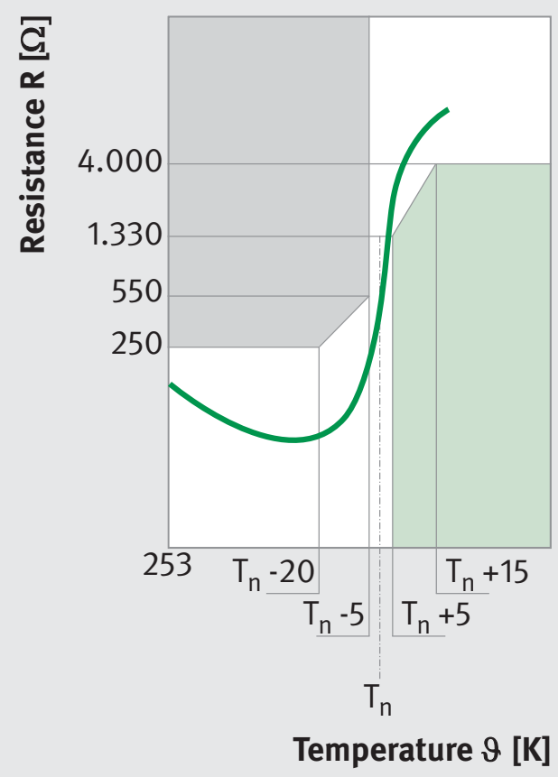
PTC temperature characteristics
In contrast to a KTY, its resistance increases very sharply when the nominal response temperature Tₙ is exceeded, increasing to many times the cold value in the process.
With three PTC elements connected in series, this behaviour also generates a clear change in the overall resistance even if only one of the elements exceeds the nominal response temperature Tₙ.
The use of three sensors ensures that, even if the motor is at a standstill under an asymmetric phase load, there is a signal for a safe shut-down. A commercially available motor protection tripping device which is connected downstream will typically trigger between 1.5 and 3.5 kOhm. In this way, overtemperature is detected to within a discrepancy of a few degrees for every winding.
The tripping devices also react if the resistance is too low in the PTC circuit, which usually indicates a defect in the monitoring circuit. It also ensures secure electrical separation between the controller and the sensors in the motor. The motor protection tripping devices are not included in the scope of supply.
PTCs are not suitable for temperature measurements. The KTY should be used here if required.
Further monitoring sensors can be integrated at the customer's request.
As a rule, PTC sensor signals must be monitored for protection against overtemperature.
11
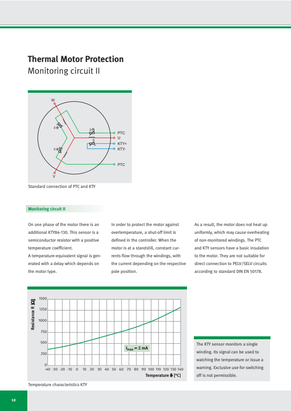
Thermal Motor Protection
Monitoring circuit II

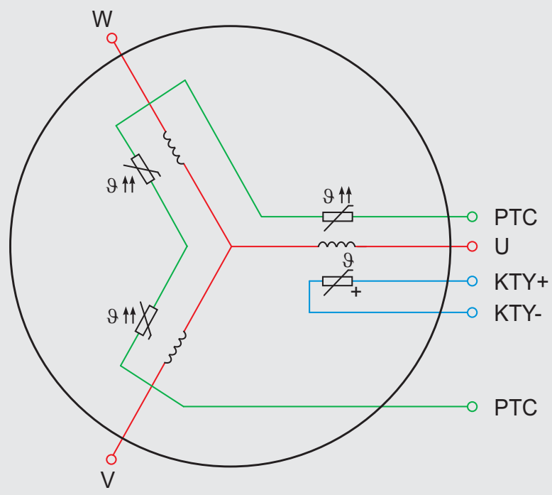
Standard connection of PTC and KTY
Monitoring circuit II
On one phase of the motor there is an additional KTY84-130. This sensor is a semiconductor resistor with a positive temperature coefficient.
In order to protect the motor against overtemperature, a shut-off limit is defined in the controller. When the motor is at a standstill, constant currents flow through the windings, with the current depending on the respective pole position.
As a result, the motor does not heat up uniformly, which may cause overheating of non-monitored windings. The PTC and KTY sensors have a basic insulation to the motor. They are not suitable for direct connection to PELV/SELV circuits according to standard DIN EN 50178.
A temperature-equivalent signal is generated with a delay which depends on the motor type.
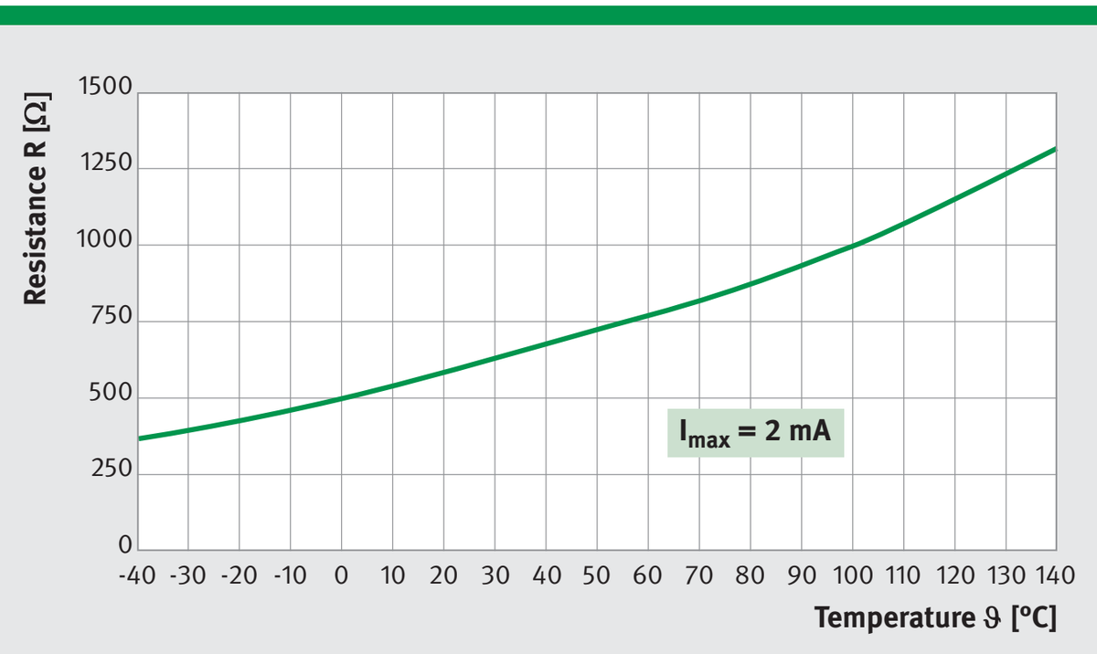
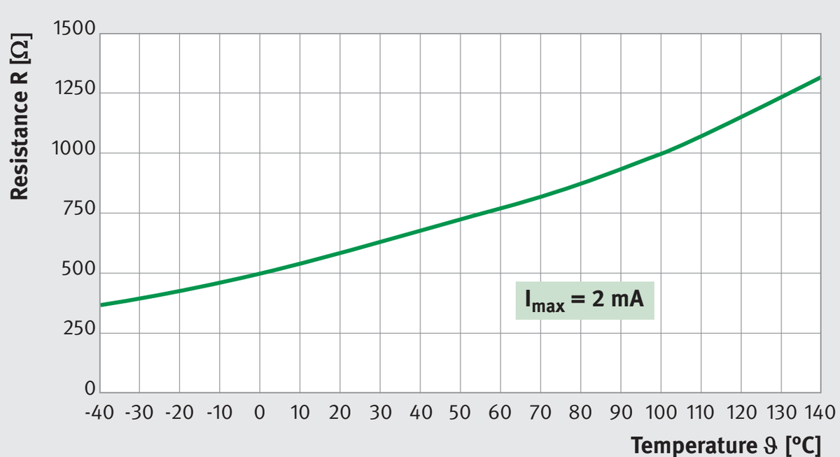
The KTY sensor monitors a single winding. Its signal can be used to watching the temperature or issue a warning. Exclusive use for switching off is not permissible.
Temperature characteristics KTY
12
Electrical Connections
The standard connections of the IDAM motors are routed through the face end. The standard cable length from the point where the cable emerges from the motor is 1000 mm. Different lengths are available upon request. The cross-section of the power cable depends on the continuous motor current and is documented in the catalogue drawing. As standard, the dimensions are laid out
for the continuous current I_c at Pₗ (non cooled) for L1A and L1B and continuous current I_cw at P_lcw (cooled) for L1C. Motor cables are available from 4G0.75 mm². The sensor cable 4 x 0.14 mm² (d = 5.1 mm) allows temperature monitoring via PTC and KTY. The wire ends are open and fitted with end sleeves. The cables which are used are UL approved and suitable for cable chains.
Motor versions with terminals (type WAGO series 236) for wires up to 1.5 mm² with end sleeves are available as an option. The cable outlets or terminals are shown in the data sheets. For terminals there is a restriction to variants without water cooling and with a continuous current of up to 16 A.
Terminal assignments
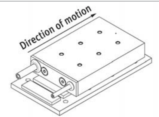
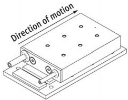
Positive direction of motor motion
| Motor | ||
|---|---|---|
| Core | Terminal | |
| U | 1 | Phase U |
| VV | 2 | Phase V |
| WWW | 3 | Phase W |
| GNYE | 4 | PE |
| BK | Shield | |
| Sensor | ||
| WH | 7 | PTC |
| BN | 8 | PTC |
| GN | 5 | + KTY |
| YE | 6 | - KTY |
On all three-phase motors the electrically positive direction of motion corresponds to a right-handed rotary field, i.e. the phase voltages are induced in the sequence U, V, W. On IDAM motors, this positive direction of motor motion is
Direction of motion with positive current feed, example: cable outlet
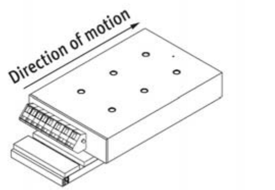
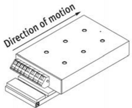
- in the direction of the side without cable(s)
- in the direction of the side without terminal(s).
| Continuous motor current I in A | Motor cable cross-section A in mm² | Diameter dk in mm | Bending radius, moving rd in mm | Bending radius, static rs in mm |
|---|---|---|---|---|
| ≤9 | 0.75 | 7.3 | 73 | 44 |
| ≤16 | 1.5 | 10 | 100 | 60 |
| ≤22 | 2.5 | 11.6 | 120 | 70 |
Direction of motion with positive current feed, example: terminal
Dimensioning of motor cables
この領域では表は抽出されませんでした。
13
Commutation
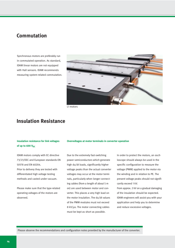
Synchronous motors are preferably run in commutated operation. As standard, IDAM linear motors are not equipped with Hall sensors. IDAM recommends measuring system-related commutation.
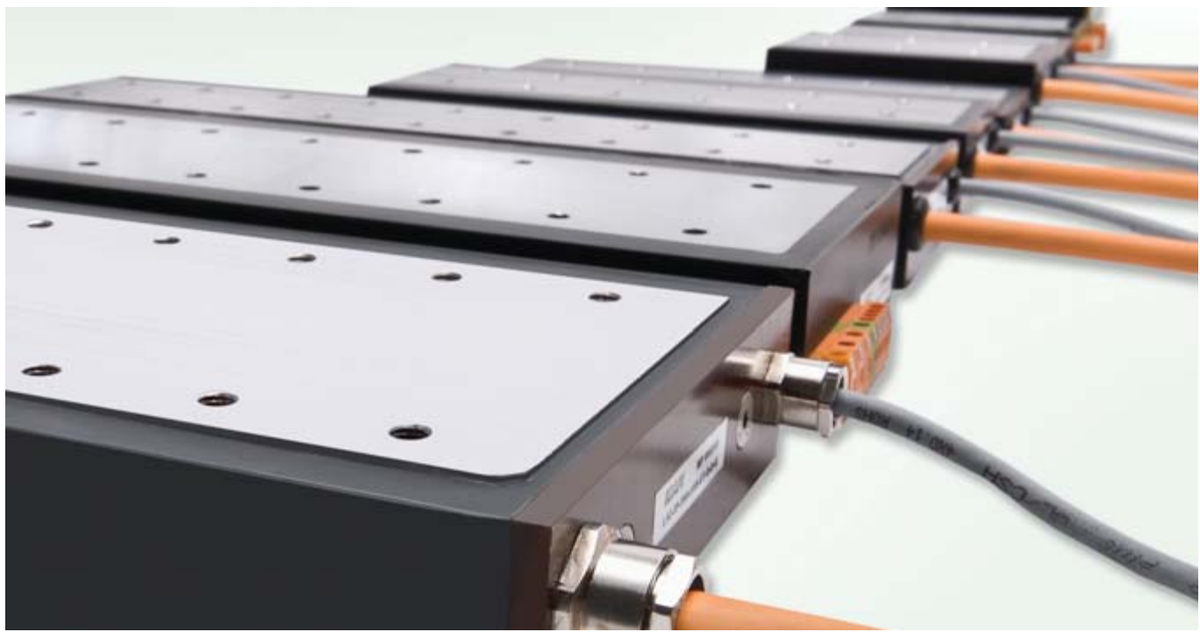
L1 motors
Insulation Resistance
Insulation resistance for link voltages of up to 600 VDC
IDAM motors comply with EC directive 73/23/EEC and European standards EN 50178 and EN 60204.
Prior to delivery they are tested with differentiated high voltage testing methods and casted under vacuum.
Please make sure that the type-related operating voltages of the motors are observed.
Overvoltages at motor terminals in converter operation
Due to the extremely fast-switching power semiconductors which generate high du/dt loads, significantly higher voltage peaks than the actual converter voltages may occur at the motor terminals, particularly when longer connecting cables (from a length of about 5 m on) are used between motor and converter. This places a very high load on the motor insulation. The du/dt values of the PWM modules must not exceed 8 kV/μs. The motor connecting cables must be kept as short as possible.
In order to protect the motors, an oscilloscope should always be used in the specific configuration to measure the voltage (PWM) applied to the motor via the winding and in relation to PE. The present voltage peaks should not significantly exceed 1 kV.
From approx. 2 kV on a gradual damaging of the insulation should be expected. IDAM engineers will assist you with your application and help you to determine and reduce excessive voltages.
Please observe the recommendations and configuration notes provided by the manufacturer of the converter.
14
Cooling and Cooling Circuits
Power losses and thermal losses
In addition to the power losses defined by the motor constant kₘ, motors are also subject to frequency-dependent losses occurring especially at higher control frequencies (above 50 Hz). These losses jointly cause the motor and other system assemblies to heat up.
The following rule applies at low control frequencies (<80 Hz) of the motors: Motors with a high motor constant kₘ produce lower power losses in relation to comparable motors with a lower motor constant.
The power losses generated during motor operation are transmitted via the motor assembly to attached components. The overall system is carefully designed to control the way in which this heat distribution is influenced and controlled through convection, conduction and radiation.
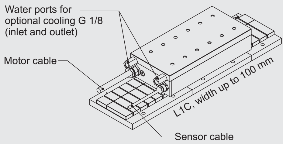
For the L1C motors, a cooling system is available as an accessory in order to improve heat dissipation.
The continuous forces of liquid-cooled motors are around twice as high as those of non cooled motors.
Motors must be designed and integrated into the machine concept in accordance with the requirements for installation space, accuracy and cooling.
Active cooling should be preferably used on machines with high performance and on equipment with highly dynamic operation and correspondingly high bearing loads.
If complete thermal separation of motor and machine is required (e.g. in order to prevent thermal distortion of the machine construction in high-precision machinery),
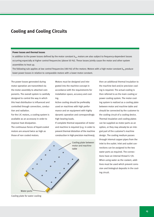
then an additional thermal insulation to the machine bed and/or precision cooling is required. The actual cooling is then referred to as the main cooling or power cooling system. The motor cooling system is realized as a cooling plate between motor and machine table and should be connected by the customer to the cooling circuit of a cooling device. Thermal insulation and cooling plates can be supplied as motor parts as an option, or they may already be an integral part of the customer's machine design. The cooling medium passes through internal copper pipes from the inlet to the outlet. Inlet and outlet connections can be assigned to the two water ports as required. The connections have an internal thread G 1/8. When using water as the coolant, additives must be used which prevent corrosion and biological deposits in the cooling circuit.
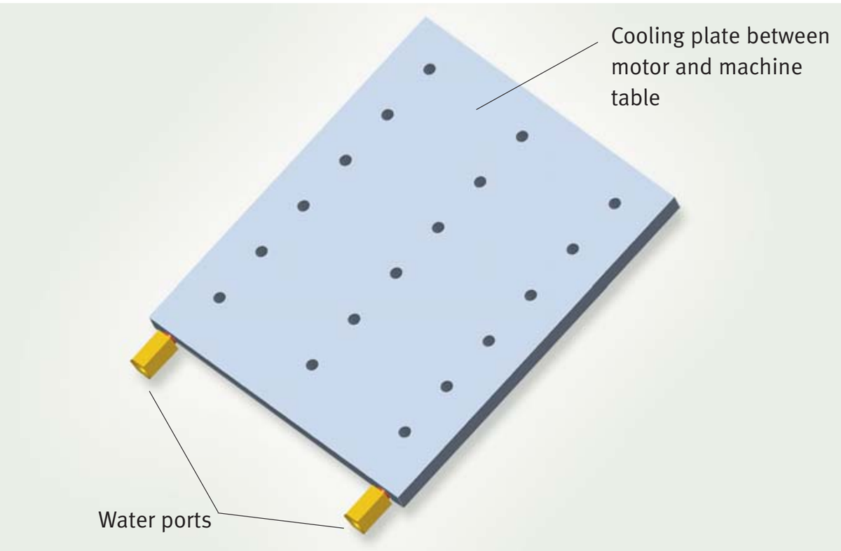
Cooling plate for water cooling
15
Dependency of Characteristic Data on the Supply Temperature of Cooling Medium
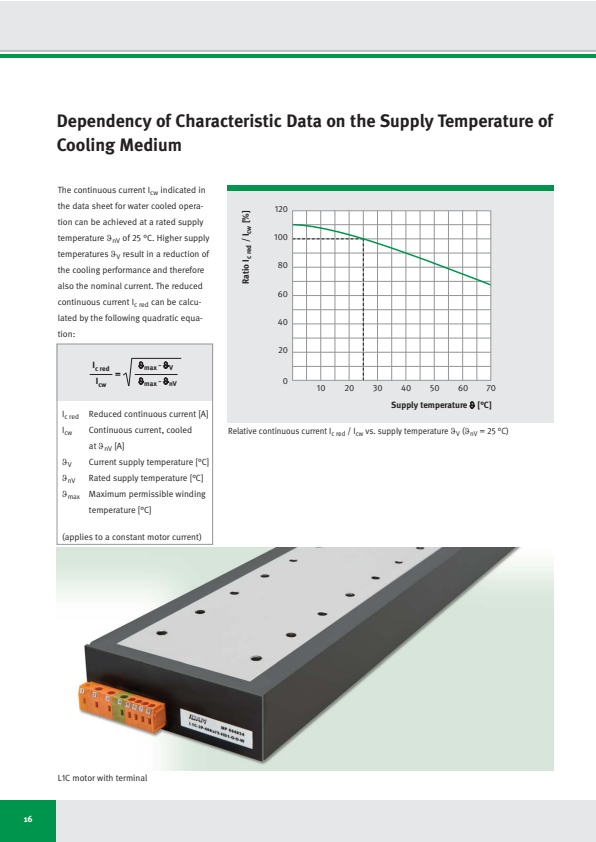
The continuous current I_cw indicated in the data sheet for water cooled operation can be achieved at a rated supply temperature θ_nV of 25 °C. Higher supply temperatures θ_V result in a reduction of the cooling performance and therefore also the nominal current. The reduced continuous current I_c red can be calculated by the following quadratic equation:
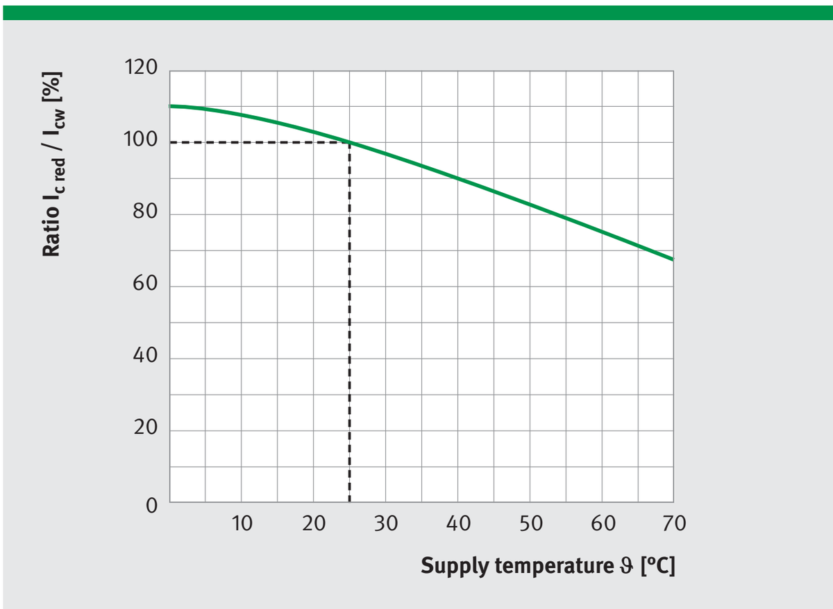
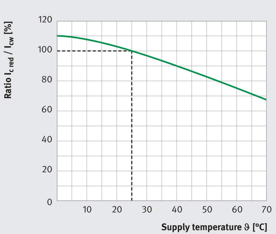
(I_c red) / I_cw = \sqrt{(ϑₘₐₓ - ϑ_V) / (ϑₘₐₓ - ϑ_nV)}
I_c red Reduced continuous current [A]
I_cw Continuous current, cooled at θ_nV [A]
Relative continuous current I_c red / I_cw vs. supply temperature θ_V (θ_nV = 25 °C)
θ_V Current supply temperature [°C]
θ_nV Rated supply temperature [°C]
θ_max Maximum permissible winding temperature [°C]
(applies to a constant motor current)
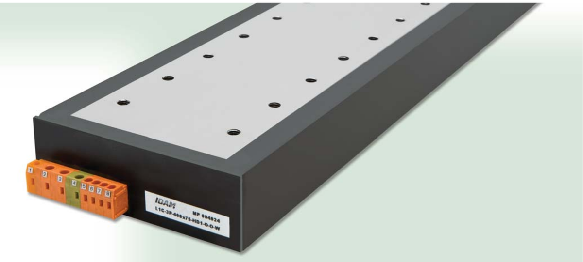
L1C motor with terminal
16
I c red Reduced continuous current [A]
I cw Continuous current, cooled at ϑ nV [A]
ϑ V Current supply temperature [°C]
ϑ nV Rated supply temperature [°C]
ϑ max Maximum permissible winding temperature [°C]
(applies to a constant motor current) (applies to a constant motor current)
Selection of Direct Drives for Linear Motions
Cycled applications
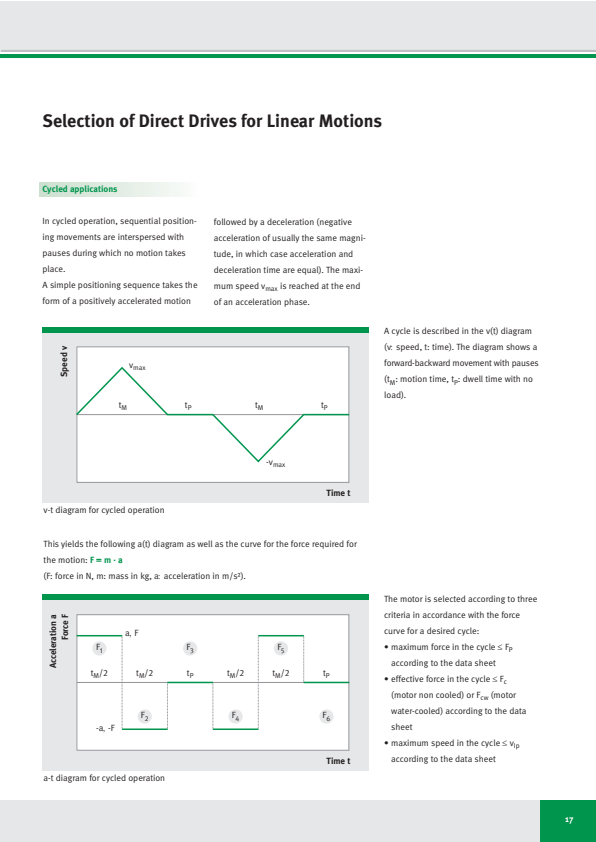
In cycled operation, sequential positioning movements are interspersed with pauses during which no motion takes place.
followed by a deceleration (negative acceleration of usually the same magnitude, in which case acceleration and deceleration time are equal). The maximum speed v_max is reached at the end of an acceleration phase.
A simple positioning sequence takes the form of a positively accelerated motion
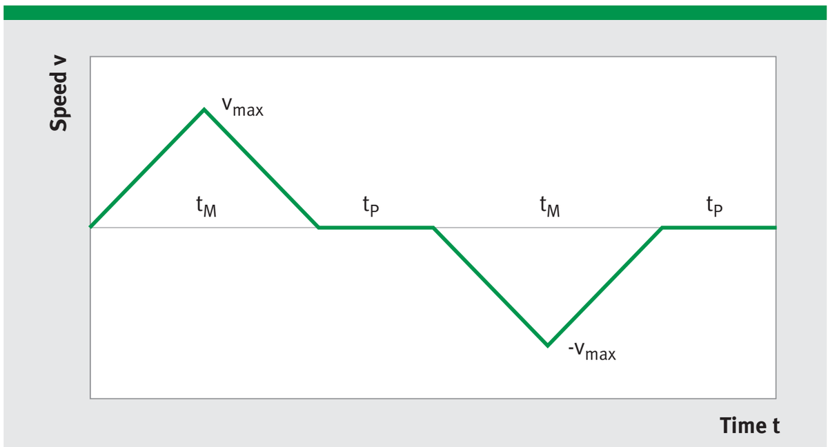
A cycle is described in the v(t) diagram (v: speed, t: time). The diagram shows a forward-backward movement with pauses (t_M: motion time, t_P: dwell time with no load).
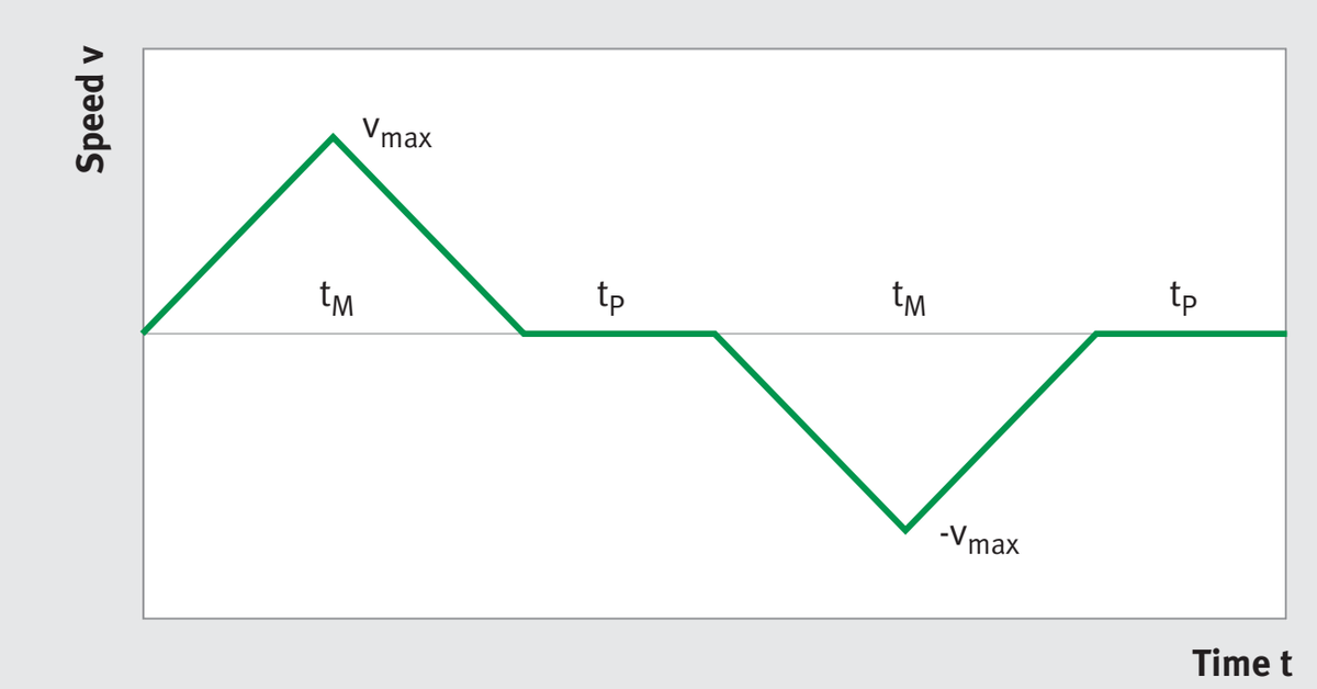
v-t diagram for cycled operation
This yields the following a(t) diagram as well as the curve for the force required for the motion: F = m · a
(F: force in N, m: mass in kg, a: acceleration in m/s²).
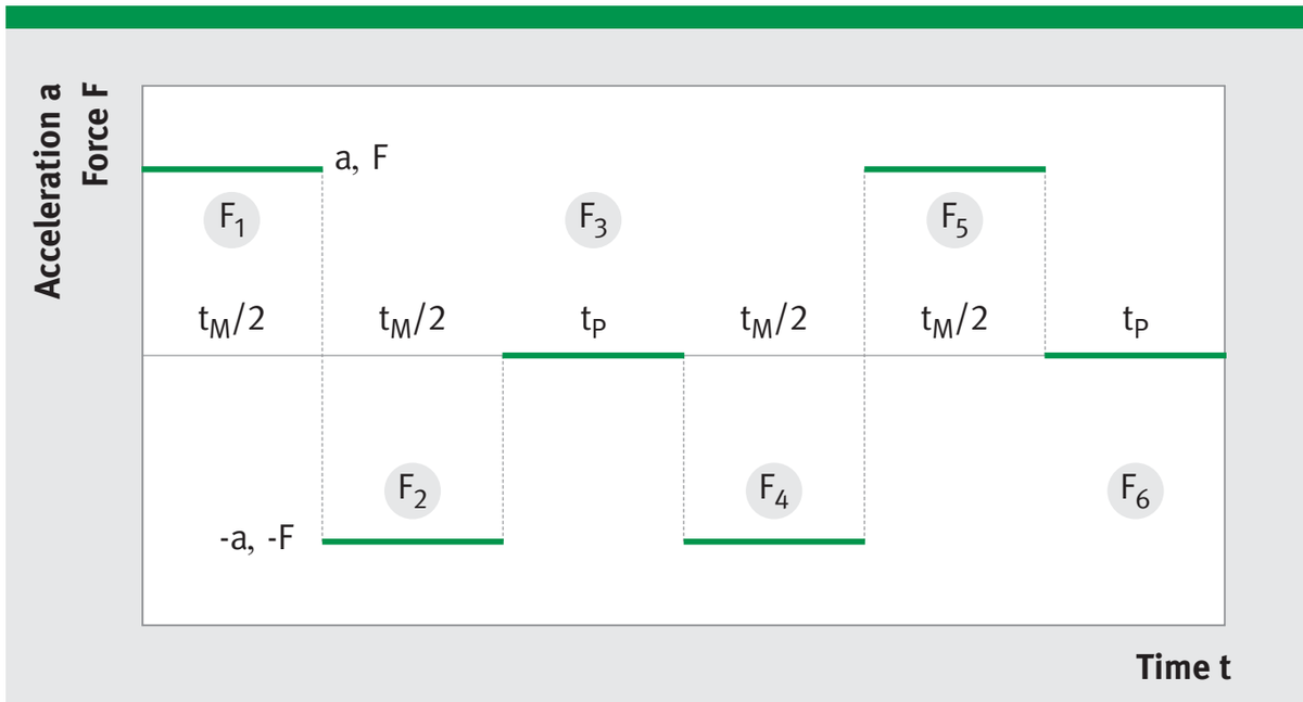
The motor is selected according to three criteria in accordance with the force curve for a desired cycle:
- maximum force in the cycle ≤ F_P according to the data sheet - effective force in the cycle ≤ F_c (motor non cooled) or F_cw (motor water-cooled) according to the data sheet - maximum speed in the cycle ≤ v_lp according to the data sheet
a-t diagram for cycled operation
17
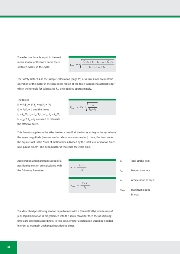
The effective force is equal to the root mean square of the force curve (here: six force cycles) in the cycle.
F_eff = √((F₁² · t₁ + F₂² · t₂ + \dots + F₆² · t₆) / (t₁ + t₂ + \dots + t₆))
The safety factor 1.4 in the sample calculation (page 19) also takes into account the operation of the motor in the non-linear region of the force-current characteristic, for which the formula for calculating F_eff only applies approximately.
The forces
F₁ = F; F₂ = -F; F₃ = 0; F₄ = -F;
F₅=F;F₆=0 and the times
t₁ = t_M/2; t₂ = t_M/2; t₃ = t_P; t₄ = t_M/2;
t₅=t_M/2;t₆=t_P are used to calculate the effective force.
F_eff = F · √(t_M / (t_M + t_P))
This formula applies to the effective force only if all the forces acting in the cycle have the same magnitude (masses and accelerations are constant). Here, the term under the square root is the “sum of motion times divided by the total sum of motion times plus pause times”. The denominator is therefore the cycle time.
Acceleration and maximum speed of a positioning motion are calculated with the following formulas:
a = (4 · x) / t_M²
vₘₐₓ = (2 · x) / t_M
x Total stroke in m
t_M Motion time in s
a Acceleration in m/s²
vₘₐₓ Maximum speed in m/s
The described positioning motion is performed with a (theoretically) infinite rate of jerk. If jerk limitation is programmed into the servo converter then the positioning times are extended accordingly. In this case, greater acceleration would be needed in order to maintain unchanged positioning times.
18
x Total stroke in m
tM Motion time in s
a Acceleration in m/s²
vmax Maximum speed in m/s
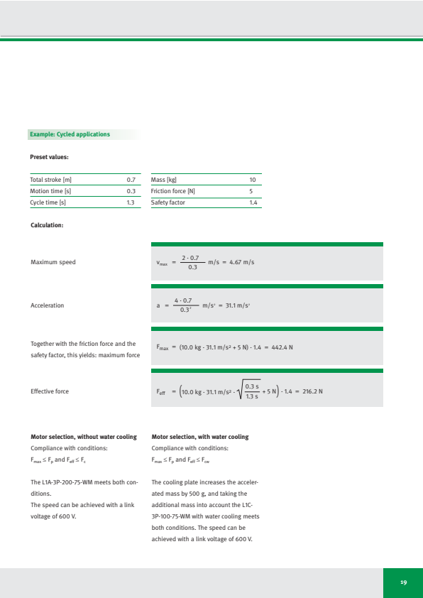
Example: Cycled applications
Preset values:
| Total stroke [m] | 0.7 |
|---|---|
| Motion time [s] | 0.3 |
| Cycle time [s] | 1.3 |
| Mass [kg] | 10 |
|---|---|
| Friction force [N] | 5 |
| Safety factor | 1.4 |
Calculation:
Maximum speed
vₘₐₓ = (2 · 0.7) / 0.3 m/s = 4.67 m/s
Acceleration
a = (4 · 0.7) / 0.3² m/s² = 31.1 m/s²
Together with the friction force and the safety factor, this yields: maximum force
Fₘₐₓ = (10.0 kg · 31.1 m/s² + 5 N) · 1.4 = 442.4 N
Effective force
F_eff = (10.0 kg · 31.1 m/s² · √((0.3 s) / (1.3 s)) + 5 N) · 1.4 = 216.2 N
Motor selection, without water cooling
Compliance with conditions:
Fₘₐₓ ≤ Fₚ and F_eff ≤ F_c
The L1A-3P-200-75-WM meets both conditions.
The speed can be achieved with a link voltage of 600 V.
Motor selection, with water cooling
Compliance with conditions:
Fₘₐₓ ≤ Fₚ and F_eff ≤ F_cw
The cooling plate increases the accelerated mass by 500 g, and taking the additional mass into account the L1C-3P-100-75-WM with water cooling meets both conditions. The speed can be achieved with a link voltage of 600 V.
19
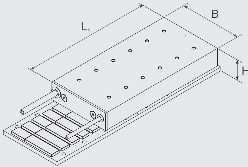
L1 Linear Motors
Sizes L1A, L1B
| Type | Length L₁ [mm] | Width B [mm] | Height H [mm] | Peak force Fₚ [N] | Continuous force non cooled Fc [N] |
|---|---|---|---|---|---|
| L1A-3P-100-25 | 113 | 57 | 31 - 0.1 | 169 | 37 |
| L1A-3P-100-50 | 113 | 82 | 31 - 0.1 | 338 | 81 |
| L1A-3P-100-75 | 113 | 107 | 31 - 0.1 | 505 | 116 |
| L1A-3P-200-25 | 208 | 57 | 31 - 0.1 | 338 | 72 |
| L1A-3P-200-50 | 208 | 82 | 31 - 0.1 | 677 | 148 |
| L1A-3P-200-75 | 208 | 107 | 31 - 0.1 | 1010 | 225 |
ページ 24 to 33
| Type | Length L₁ [mm] | Width B [mm] | Height H [mm] | Peak force Fₚ [N] | Continuous force non cooled Fc [N] |
|---|---|---|---|---|---|
| L1B-3P-100-25 | 113 | 57 | 39 - 0.1 | 171 | 52 |
| L1B-3P-100-50 | 113 | 82 | 39 - 0.1 | 340 | 106 |
| L1B-3P-100-75 | 113 | 107 | 39 - 0.1 | 507 | 159 |
| L1B-3P-200-25 | 208 | 57 | 39 - 0.1 | 341 | 100 |
| L1B-3P-200-50 | 208 | 82 | 39 - 0.1 | 679 | 200 |
| L1B-3P-200-75 | 208 | 107 | 39 - 0.1 | 1014 | 299 |
| L1B-3P-300-25 | 303 | 57 | 39 - 0.1 | 512 | 147 |
| L1B-3P-300-50 | 303 | 82 | 39 - 0.1 | 1019 | 292 |
| L1B-3P-300-75 | 303 | 107 | 39 - 0.1 | 1521 | 436 |
ページ 34 to 47
20
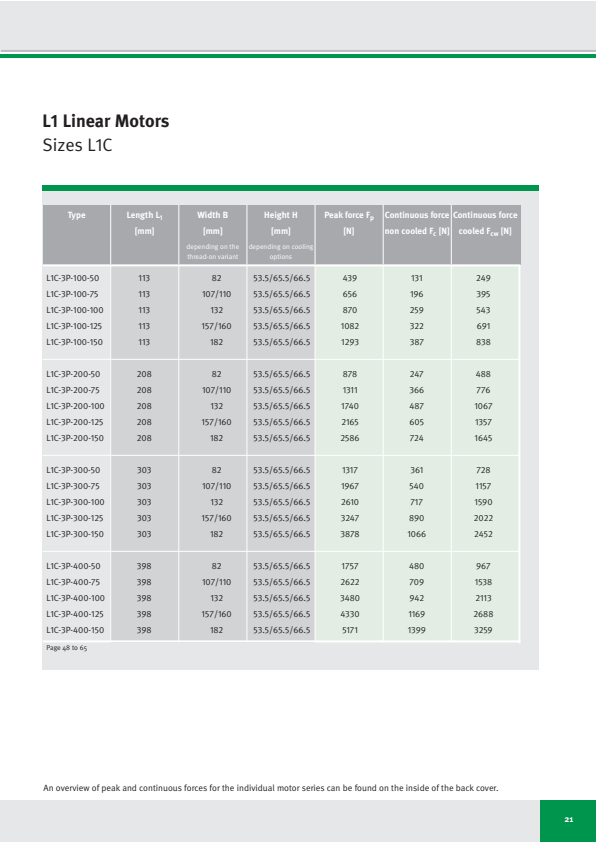
L1 Linear Motors
Sizes L1C
| Type | Length L₁ [mm] | Width B [mm] depending on the thread-on variant | Height H [mm] depending on cooling options | Peak force Fp [N] | Continuous force non cooled Fc [N] | Continuous force cooled Fcw [N] |
|---|---|---|---|---|---|---|
| L1C-3P-100-50 | 113 | 82 | 53.5/65.5/66.5 | 439 | 131 | 249 |
| L1C-3P-100-75 | 113 | 107/110 | 53.5/65.5/66.5 | 656 | 196 | 395 |
| L1C-3P-100-100 | 113 | 132 | 53.5/65.5/66.5 | 870 | 259 | 543 |
| L1C-3P-100-125 | 113 | 157/160 | 53.5/65.5/66.5 | 1082 | 322 | 691 |
| L1C-3P-100-150 | 113 | 182 | 53.5/65.5/66.5 | 1293 | 387 | 838 |
| L1C-3P-200-50 | 208 | 82 | 53.5/65.5/66.5 | 878 | 247 | 488 |
| L1C-3P-200-75 | 208 | 107/110 | 53.5/65.5/66.5 | 1311 | 366 | 776 |
| L1C-3P-200-100 | 208 | 132 | 53.5/65.5/66.5 | 1740 | 487 | 1067 |
| L1C-3P-200-125 | 208 | 157/160 | 53.5/65.5/66.5 | 2165 | 605 | 1357 |
| L1C-3P-200-150 | 208 | 182 | 53.5/65.5/66.5 | 2586 | 724 | 1645 |
| L1C-3P-300-50 | 303 | 82 | 53.5/65.5/66.5 | 1317 | 361 | 728 |
| L1C-3P-300-75 | 303 | 107/110 | 53.5/65.5/66.5 | 1967 | 540 | 1157 |
| L1C-3P-300-100 | 303 | 132 | 53.5/65.5/66.5 | 2610 | 717 | 1590 |
| L1C-3P-300-125 | 303 | 157/160 | 53.5/65.5/66.5 | 3247 | 890 | 2022 |
| L1C-3P-300-150 | 303 | 182 | 53.5/65.5/66.5 | 3878 | 1066 | 2452 |
| L1C-3P-400-50 | 398 | 82 | 53.5/65.5/66.5 | 1757 | 480 | 967 |
| L1C-3P-400-75 | 398 | 107/110 | 53.5/65.5/66.5 | 2622 | 709 | 1538 |
| L1C-3P-400-100 | 398 | 132 | 53.5/65.5/66.5 | 3480 | 942 | 2113 |
| L1C-3P-400-125 | 398 | 157/160 | 53.5/65.5/66.5 | 4330 | 1169 | 2688 |
| L1C-3P-400-150 | 398 | 182 | 53.5/65.5/66.5 | 5171 | 1399 | 3259 |
| ページ 48 to 65 | ||||||
An overview of peak and continuous forces for the individual motor series can be found on the inside of the back cover.
21
L1 Linear Motors
Features
L1 linear motors are slotted, permanent magnet-excited AC synchronous motors. The coils of the primary part are fitted in slots on the armature stamping. The secondary part comprises an iron base onto which permanent magnets are fastened.
L1 motors are optimised for ultimate efficiency, which means: maximum force in the available installation space at nominal speed with low power losses.
They excel by low accelerated mass and compact dimensions.
The benefits of the L1 motors include an optimal design and thermal integration into the peripheral structure as well as comprehensive adjustment to the overall requirements of the drive system.
Linear motor: L1A
- Installation height of only 31 mm
- Very compact design
- Excellent force-to-mass ratio
Linear motor: L1B
- Installation height of only 39 mm
- Applications with optimised thermal power loss in comparison to L1A
- Higher continuous force than L1A with the same heat generation
Linear motor: L1C
- Installation height 53.5 mm (without cooling plate), 65.5 mm (with cooling plate) or 66.5 mm (with cooling plate and thermal insulation)
- Applications with optimised thermal power loss in comparison to L1B
- Higher continuous force than L1B with equal heat generation
- Cooling options: Cooling plate, thermal insulation to machine bed
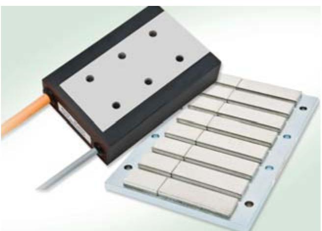
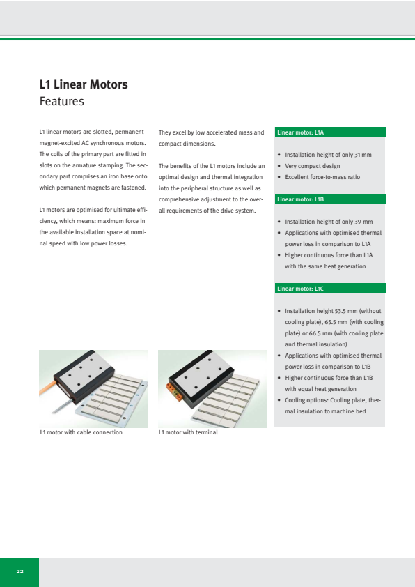
L1 motor with cable connection
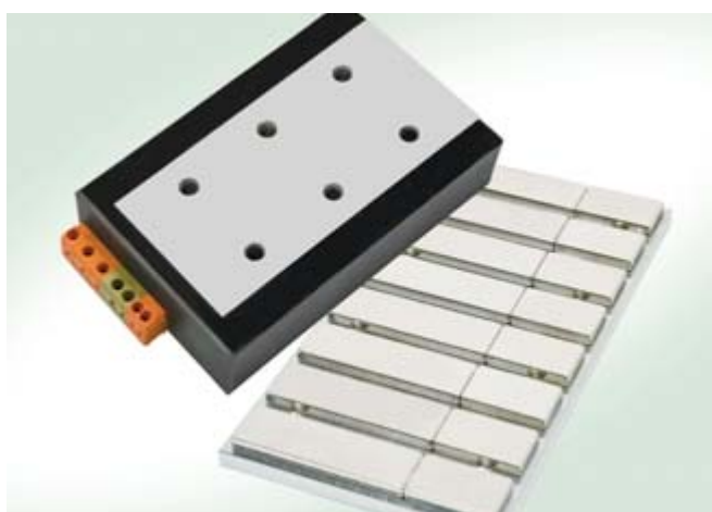
L1 motor with terminal
22
• Installation height of only 31 mm
• Very compact design
• Excellent force-to-mass ratio
Linear motor: L1B
• Installation height of only 39 mm
• Applications with optimised thermal power loss in comparison to L1A
• Higher continuous force than L1A with the same heat generation
Linear motor: L1C
• Installation height 53.5 mm (without cooling plate), 65.5 mm (with cooling plate) or 66.5 mm (with cooling plate and thermal insulation)
• Applications with optimised thermal power loss in comparison to L1B
• Higher continuous force than L1B with equal heat generation
• Cooling options: Cooling plate, thermal insulation to machine bed
L1 Linear Motors
Areas of use, applications, advantages
Areas of use
- Semiconductor industry
- Printed circuit-board processing
- Packaging industry
- Food industry
- Machine tools
- Placement at production lines
- Assembly and handling technology
Applications
Applications with high requirements in terms of accuracy and dynamic performance, plus with limited installation space
- Feed systems
- Laser/water jet cutting systems
- Manipulator operation
- PCB handling systems
- Wafer positioning systems
- AOI systems
Advantages
- High acceleration and deceleration capacity thanks to a significantly better force-to-mass ratio than conventional motors
- Higher speed than conventional motors
- High static and dynamic load rigidity
- Accurate positioning without overshooting
- Excellent constant-velocity properties
- Compact design
- Maintenance-free drive with zero backlash
- Active cooling options
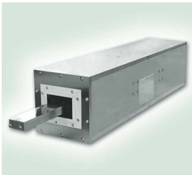
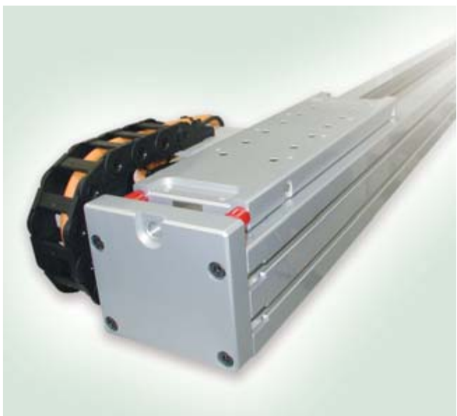
LDDS60 push rod system with a stroke of 170 mm
MKUVS42-LM - high-speed handling
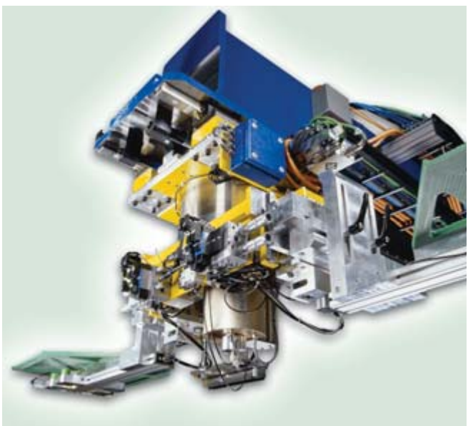
Handling system precision blanking with direct drives
23
● Semiconductor industry Applications with high requirements ● High acceleration and deceleration
capacity thanks to a significantly
better force-to-mass ratio than
conventional motors
● Printed circuit-board processing in terms of accuracy and dynamic per-
● Packaging industry formance, plus with limited installation
● Food industry space
● Machine tools ● Feed systems ● Higher speed than conventional
motors
● Assembly and handling technology ● Laser/water jet cutting systems
● Manipulator operation ● High static and dynamic load rigidity
● PCB handling systems ● Accurate positioning without
overshooting
● Wafer positioning systems
● AOI systems ● Excellent constant-velocity properties
● Compact design
● Maintenance-free drive with zero
backlash
● Active cooling options
• Semiconductor industry
• Printed circuit-board processing
• Packaging industry
• Food industry
• Machine tools
• Placement at production lines
• Assembly and handling technology Applications with high requirements
in terms of accuracy and dynamic per-
formance, plus with limited installation
space
• Feed systems
• Laser/water jet cutting systems
• Manipulator operation
• PCB handling systems
• Wafer positioning systems
• AOI systems • High acceleration and deceleration
capacity thanks to a significantly
better force-to-mass ratio than
conventional motors
• Higher speed than conventional
motors
• High static and dynamic load rigidity
• Accurate positioning without
overshooting
• Excellent constant-velocity properties
• Compact design
• Maintenance-free drive with zero
backlash
• Active cooling options
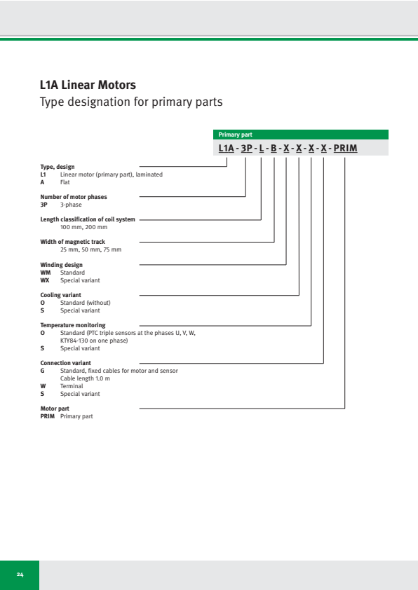
L1A Linear Motors
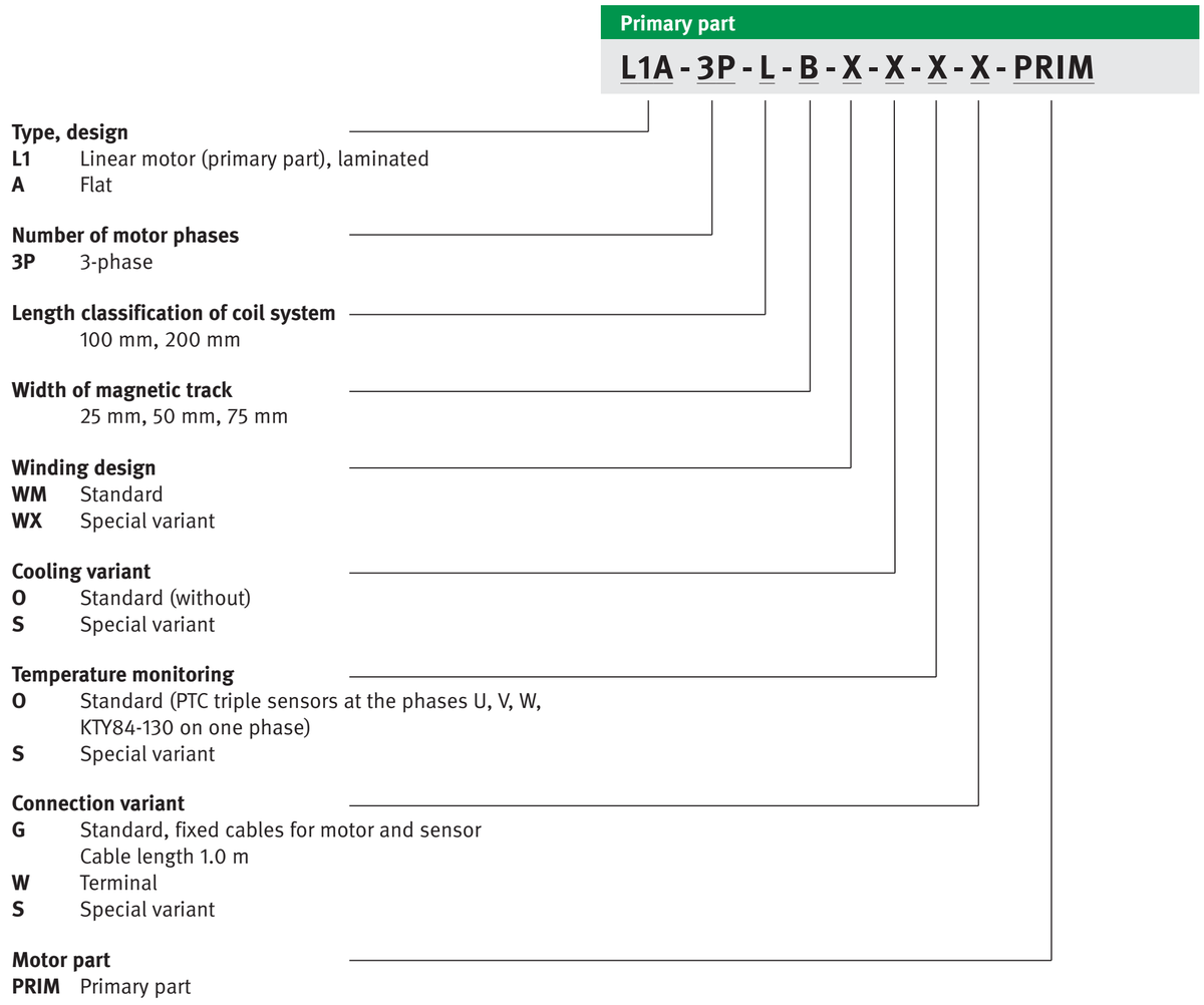
Type designation for primary parts
24
L1A - 3P - L - B - X - X - X - X - PRIM
Type, design L1 Linear motor (primary part), laminated
A Flat L1A
Number of motor phases 3P 3-phase 3P
Length classification of coil system 100 mm, 200 mm L
Width of magnetic track 25 mm, 50 mm, 75 mm B
Winding design WM Standard
WX Special variant X
Cooling variant O Standard (without)
S Special variant X
Temperature monitoring O Standard (PTC triple sensors at the phases U, V, W,
KTY84-130 on one phase)
S Special variant X
Connection variant G Standard, fixed cables for motor and sensor
Cable length 1.0 m
W Terminal
S Special variant X
Motor part PRIM Primary part PRIM
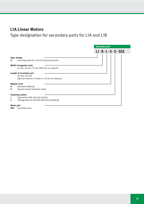
L1A Linear Motors
Type designation for secondary parts for L1A and L1B
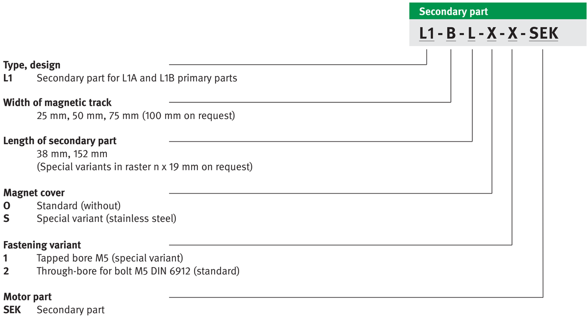
同じ画像がページ 35 にも表示されています
25
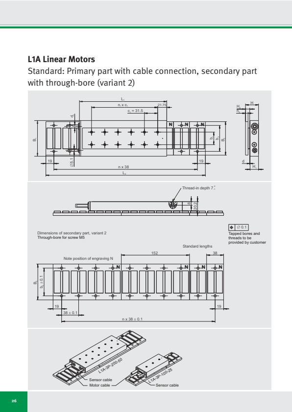
L1A Linear Motors
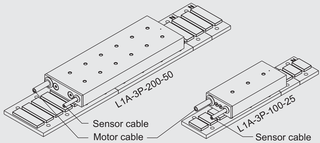
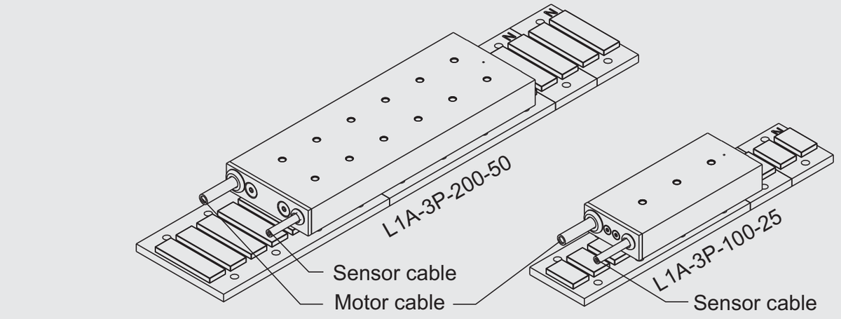
Standard: Primary part with cable connection, secondary part with through-bore (variant 2)
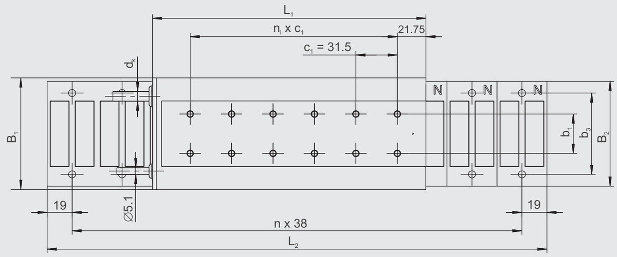

⊕ ∅ 0.1
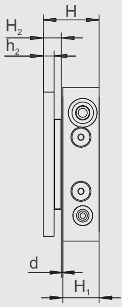
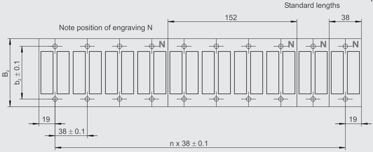
Dimensions of secondary part, variant 2
Through-bore for screw M5
Tapped bores and threads to be provided by customer
26
L1A Linear Motors
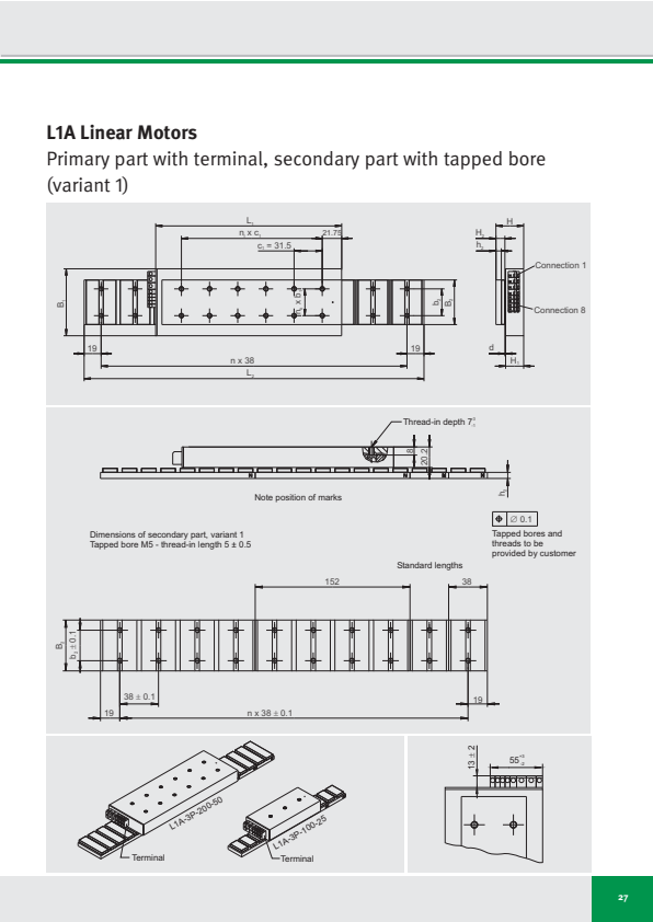
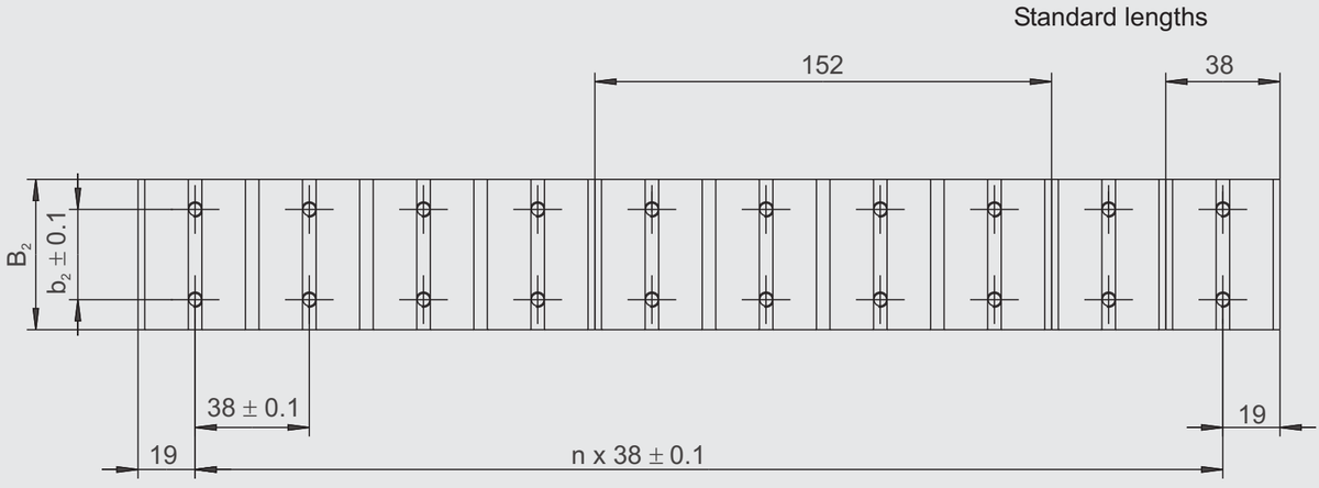
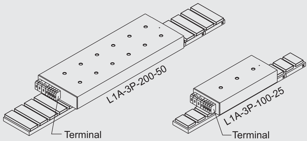
Primary part with terminal, secondary part with tapped bore (variant 1)
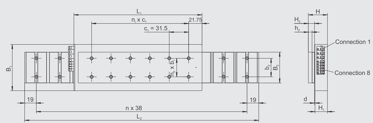
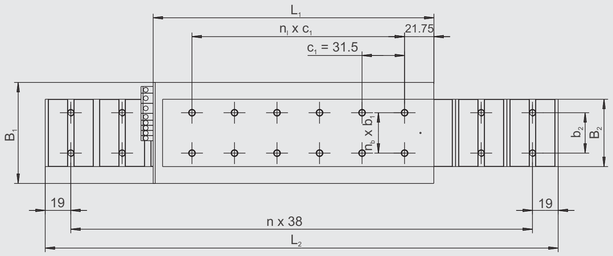
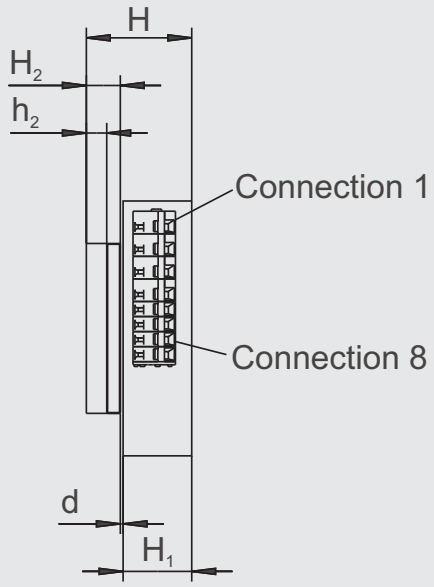
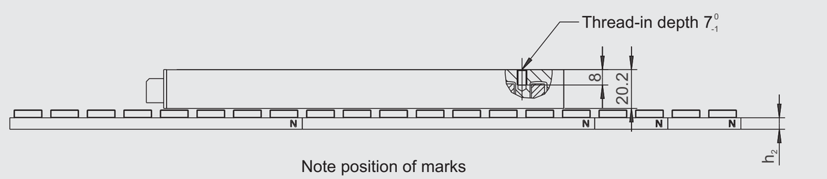
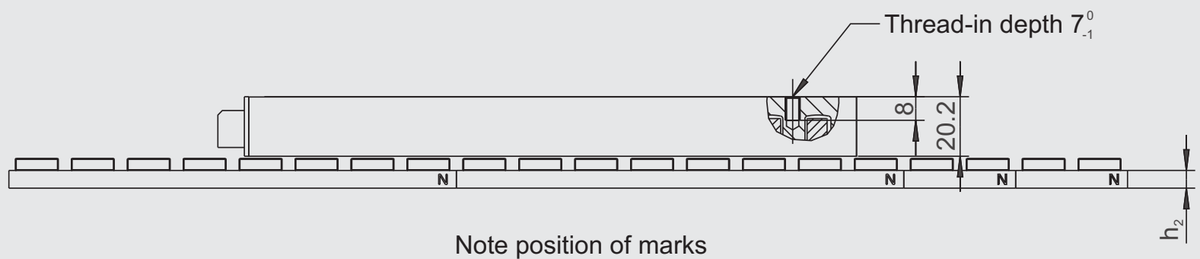
Dimensions of secondary part, variant 1
Tapped bore M5 - thread-in length 5 ± 0.5
Tapped bores and threads to be provided by customer
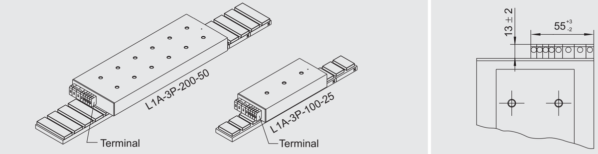
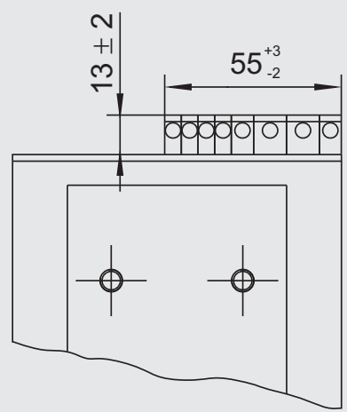
同じ画像がページ 37 にも表示されています
27
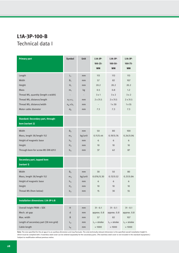
L1A-3P-100-B
Technical data I
| Primary part | Symbol | Unit | L1A-3P-100-25-WM | L1A-3P-100-50-WM | L1A-3P-100-75-WM |
|---|---|---|---|---|---|
| Length | L₁ | mm | 113 | 113 | 113 |
| Width | B₁ | mm | 57 | 82 | 107 |
| Height | H₁ | mm | 20.2 | 20.2 | 20.2 |
| Mass | m₁ | kg | 0.5 | 0.8 | 1.2 |
| Thread M5, quantity (length x width) | - | - | 3 x 1 | 3 x 2 | 3 x 2 |
| Thread M5, distance/length | n₁ x c₁ | mm | 2 x 31.5 | 2 x 31.5 | 2 x 31.5 |
| Thread M5, distance/width | n_b x b₁ | mm | - | 1 x 30 | 1 x 55 |
| Motor cable diameter | d_K | mm | 7.3 | 7.3 | 7.3 |
| Standard: Secondary part, through-bore (variant 2) | |||||
| Width | B₂ | mm | 50 | 80 | 100 |
| Mass, length 38/length 152 | m₂ | kg/unit | 0.11/0.44 | 0.19/0.76 | 0.24/0.96 |
| Height of magnetic base | h₂ | mm | 6 | 6 | 6 |
| Height | H₂ | mm | 10 | 10 | 10 |
| Through-bore for screw M5 DIN 6912 | b₃ | mm | 37 | 62 | 87 |
| Secondary part, tapped bore (variant 1) | |||||
| Width | B₂ | mm | 30 | 50 | 80 |
| Mass, length 38/length 152 | m₂ | kg/unit | 0.076/0.30 | 0.13/0.52 | 0.21/0.84 |
| Height of magnetic base | h₂ | mm | 6 | 6 | 6 |
| Height | H₂ | mm | 10 | 10 | 10 |
| Thread M5 (from below) | b₂ | mm | 15 | 30 | 55 |
| Installation dimensions: L1A-3P-L-B | |||||
| Overall height PRIM + SEK | H | mm | 31 - 0.1 | 31 - 0.1 | 31 - 0.1 |
| Mech. air gap | d | mm | approx. 0.8 | approx. 0.8 | approx. 0.8 |
| Max. width | B | mm | 57 | 82 | 107 |
| Length of secondary part (38 mm grid) | L₂ | mm | L₁ + stroke | L₁ + stroke | L₁ + stroke |
| Cable length | L_K | mm | ≈ 1000 | ≈ 1000 | ≈ 1000 |
Note: The size specified for the air gap d is an auxiliary dimension and may fluctuate. The only technically relevant dimension is the specified overall installation height H, which must be complied with. A stainless steel cover can be ordered separately for the secondary parts. (The stainless steel cover is not included in the standard equipment.) Subject to modification without previous notice.
28
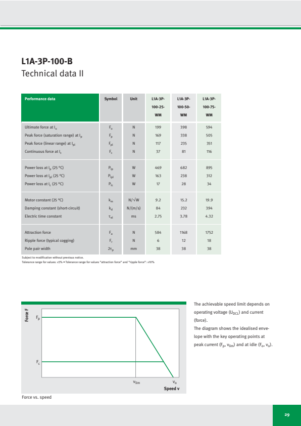
L1A-3P-100-B
Technical data II
| Performance data | Symbol | Unit | L1A-3P-100-25-WM | L1A-3P-100-50-WM | L1A-3P-100-75-WM |
|---|---|---|---|---|---|
| Ultimate force at Iu | Fu | N | 199 | 398 | 594 |
| Peak force (saturation range) at Ip | Fp | N | 169 | 338 | 505 |
| Peak force (linear range) at Ipl | Fpl | N | 117 | 235 | 351 |
| Continuous force at Ic | Fc | N | 37 | 81 | 116 |
| Power loss at Ip (25 °C) | Plp | W | 469 | 682 | 895 |
| Power loss at Ipl (25 °C) | Plpl | W | 163 | 238 | 312 |
| Power loss at Ic (25 °C) | Plc | W | 17 | 28 | 34 |
| Motor constant (25 °C) | km | N/√W | 9.2 | 15.2 | 19.9 |
| Damping constant (short-circuit) | kd | N/(m/s) | 84 | 232 | 394 |
| Electric time constant | τel | ms | 2.75 | 3.78 | 4.32 |
| Attraction force | Fa | N | 584 | 1168 | 1752 |
| Ripple force (typical cogging) | Fr | N | 6 | 12 | 18 |
| Pole pair width | 2τp | mm | 38 | 38 | 38 |
Subject to modification without previous notice.
Tolerance range for values: ±5% • Tolerance range for values “attraction force” and “ripple force”: ±10%
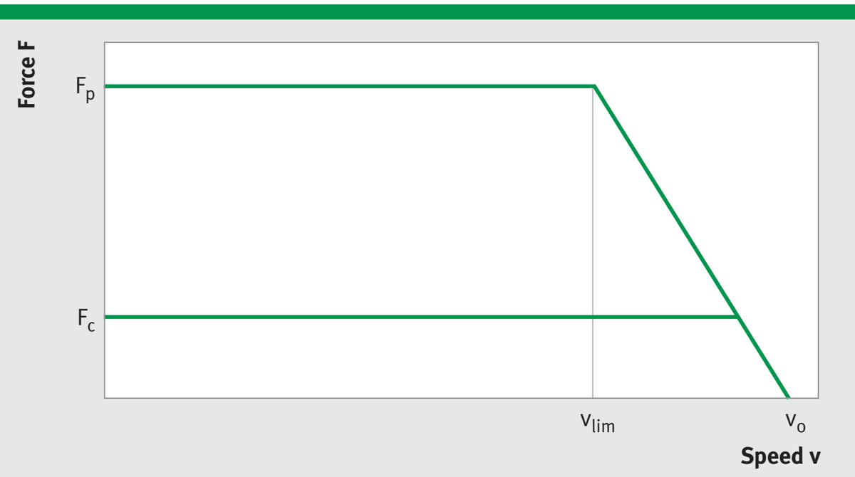
Force vs. speed
The achievable speed limit depends on operating voltage (U_DCL) and current (force).
The diagram shows the idealised envelope with the key operating points at peak current (Fₚ, vₗᵢₘ) and at idle (Fₒ, vₒ).
29
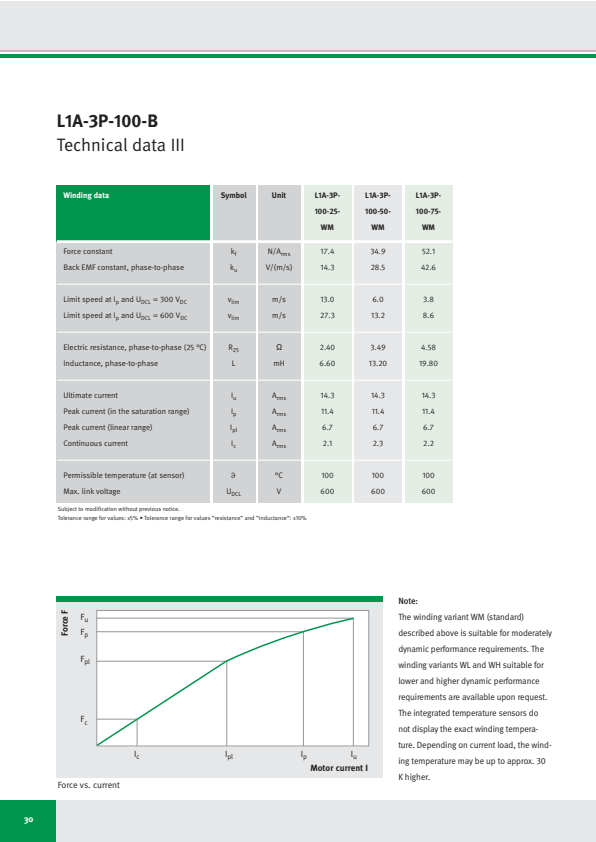
L1A-3P-100-B
Technical data III
| Winding data | Symbol | Unit | L1A-3P-100-25-WM | L1A-3P-100-50-WM | L1A-3P-100-75-WM |
|---|---|---|---|---|---|
| Force constant | kf | N/Arms | 17.4 | 34.9 | 52.1 |
| Back EMF constant, phase-to-phase | ku | V/(m/s) | 14.3 | 28.5 | 42.6 |
| Limit speed at Ip and UDCL = 300 VDC | vlim | m/s | 13.0 | 6.0 | 3.8 |
| Limit speed at Ip and UDCL = 600 VDC | vlim | m/s | 27.3 | 13.2 | 8.6 |
| Electric resistance, phase-to-phase (25 °C) | R25 | Ω | 2.40 | 3.49 | 4.58 |
| Inductance, phase-to-phase | L | mH | 6.60 | 13.20 | 19.80 |
| Ultimate current | Iu | Arms | 14.3 | 14.3 | 14.3 |
| Peak current (in the saturation range) | Ip | Arms | 11.4 | 11.4 | 11.4 |
| Peak current (linear range) | Ipl | Arms | 6.7 | 6.7 | 6.7 |
| Continuous current | Ic | Arms | 2.1 | 2.3 | 2.2 |
| Permissible temperature (at sensor) | ϑ | °C | 100 | 100 | 100 |
| Max. link voltage | UDCL | V | 600 | 600 | 600 |
Subject to modification without previous notice.
Tolerance range for values: ±5% • Tolerance range for values "resistance" and "inductance": ±10%
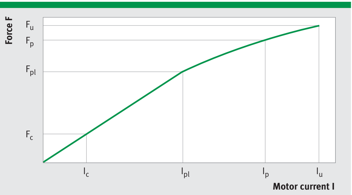
Force vs. current
Note:
The winding variant WM (standard) described above is suitable for moderately dynamic performance requirements. The winding variants WL and WH suitable for lower and higher dynamic performance requirements are available upon request. The integrated temperature sensors do not display the exact winding temperature. Depending on current load, the winding temperature may be up to approx. 30 K higher.
30
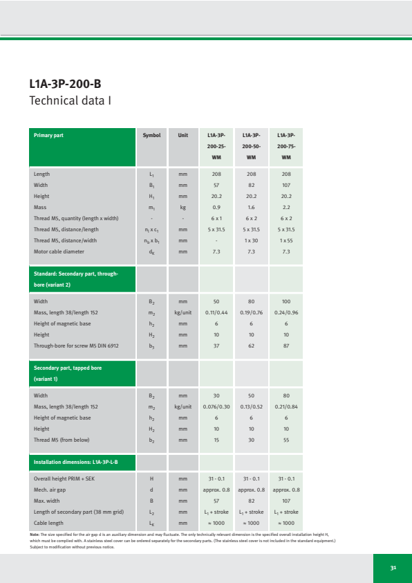
L1A-3P-200-B
Technical data I
| Primary part | Symbol | Unit | L1A-3P- 200-25- WM | L1A-3P- 200-50- WM | L1A-3P- 200-75- WM |
|---|---|---|---|---|---|
| Length | L₁ | mm | 208 | 208 | 208 |
| Width | B₁ | mm | 57 | 82 | 107 |
| Height | H₁ | mm | 20.2 | 20.2 | 20.2 |
| Mass | m₁ | kg | 0.9 | 1.6 | 2.2 |
| Thread M5, quantity (length x width) | - | - | 6 x 1 | 6 x 2 | 6 x 2 |
| Thread M5, distance/length | nₗ x c₁ | mm | 5 x 31.5 | 5 x 31.5 | 5 x 31.5 |
| Thread M5, distance/width | n_b x b₁ | mm | - | 1 x 30 | 1 x 55 |
| Motor cable diameter | d_K | mm | 7.3 | 7.3 | 7.3 |
| Standard: Secondary part, through- bore (variant 2) | |||||
| Width | B₂ | mm | 50 | 80 | 100 |
| Mass, length 38/length 152 | m₂ | kg/unit | 0.11/0.44 | 0.19/0.76 | 0.24/0.96 |
| Height of magnetic base | h₂ | mm | 6 | 6 | 6 |
| Height | H₂ | mm | 10 | 10 | 10 |
| Through-bore for screw M5 DIN 6912 | b₃ | mm | 37 | 62 | 87 |
| Secondary part, tapped bore (variant 1) | |||||
| Width | B₂ | mm | 30 | 50 | 80 |
| Mass, length 38/length 152 | m₂ | kg/unit | 0.076/0.30 | 0.13/0.52 | 0.21/0.84 |
| Height of magnetic base | h₂ | mm | 6 | 6 | 6 |
| Height | H₂ | mm | 10 | 10 | 10 |
| Thread M5 (from below) | b₂ | mm | 15 | 30 | 55 |
| Thread M5 (from below) | b₂ | mm | 15 | 30 | 55 |
| Installation dimensions: L1A-3P-L-B | |||||
| Overall height PRIM + SEK | H | mm | 31 - 0.1 | 31 - 0.1 | 31 - 0.1 |
| Mech. air gap | d | mm | approx. 0.8 | approx. 0.8 | approx. 0.8 |
| Max. width | B | mm | 57 | 82 | 107 |
| Length of secondary part (38 mm grid) | L₂ | mm | L₁ + stroke | L₁ + stroke | L₁ + stroke |
| Cable length | L_K | mm | ≈ 1000 | ≈ 1000 | ≈ 1000 |
Note: The size specified for the air gap d is an auxiliary dimension and may fluctuate. The only technically relevant dimension is the specified overall installation height H, which must be complied with. A stainless steel cover can be ordered separately for the secondary parts. (The stainless steel cover is not included in the standard equipment.) Subject to modification without previous notice.
31
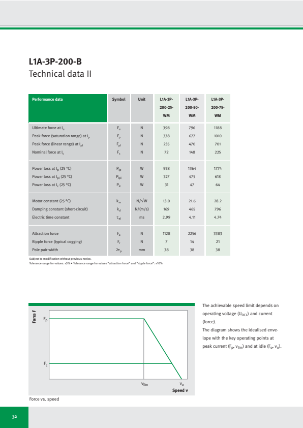
L1A-3P-200-B
Technical data II
| Performance data | Symbol | Unit | L1A-3P-200-25-WM | L1A-3P-200-50-WM | L1A-3P-200-75-WM |
|---|---|---|---|---|---|
| Ultimate force at Iu | Fu | N | 398 | 796 | 1188 |
| Peak force (saturation range) at Ip | Fp | N | 338 | 677 | 1010 |
| Peak force (linear range) at Ipl | Fpl | N | 235 | 470 | 701 |
| Nominal force at Ic | Fc | N | 72 | 148 | 225 |
| Power loss at Ip (25 °C) | Plp | W | 938 | 1364 | 1774 |
| Power loss at Ipl (25 °C) | Plpl | W | 327 | 475 | 618 |
| Power loss at Ic (25 °C) | Plc | W | 31 | 47 | 64 |
| Motor constant (25 °C) | km | N/√W | 13.0 | 21.6 | 28.2 |
| Damping constant (short-circuit) | kd | N/(m/s) | 169 | 465 | 796 |
| Electric time constant | τel | ms | 2.99 | 4.11 | 4.74 |
| Attraction force | Fa | N | 1128 | 2256 | 3383 |
| Ripple force (typical cogging) | Fr | N | 7 | 14 | 21 |
| Pole pair width | 2τp | mm | 38 | 38 | 38 |
Subject to modification without previous notice.
Tolerance range for values: ±5% • Tolerance range for values “attraction force” and “ripple force”: ±10%
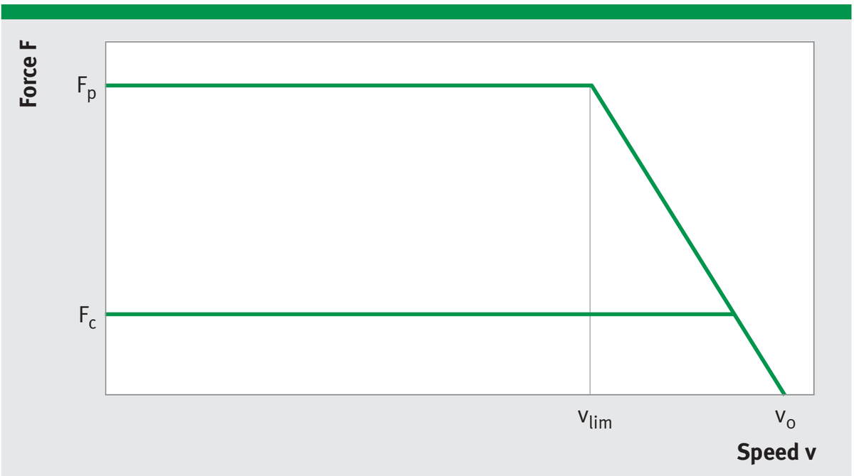
Force vs. speed
The achievable speed limit depends on operating voltage (U_DCL) and current (force).
The diagram shows the idealised envelope with the key operating points at peak current (Fₚ, vₗᵢₘ) and at idle (Fₒ, vₒ).
32
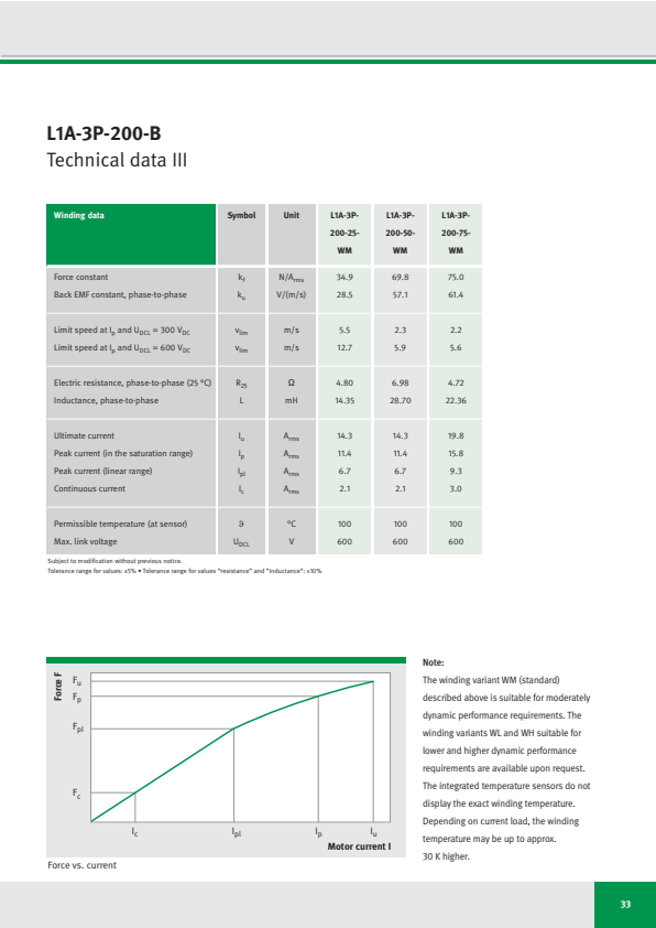
L1A-3P-200-B
Technical data III
| Winding data | Symbol | Unit | L1A-3P-200-25-WM | L1A-3P-200-50-WM | L1A-3P-200-75-WM |
|---|---|---|---|---|---|
| Force constant | k_f | N/A_rms | 34.9 | 69.8 | 75.0 |
| Back EMF constant, phase-to-phase | k_u | V/(m/s) | 28.5 | 57.1 | 61.4 |
| Limit speed at I_p and U_DCL = 300 V_DC | v_lim | m/s | 5.5 | 2.3 | 2.2 |
| Limit speed at I_p and U_DCL = 600 V_DC | v_lim | m/s | 12.7 | 5.9 | 5.6 |
| Electric resistance, phase-to-phase (25 °C) | R_25 | Ω | 4.80 | 6.98 | 4.72 |
| Inductance, phase-to-phase | L | mH | 14.35 | 28.70 | 22.36 |
| Ultimate current | I_u | A_rms | 14.3 | 14.3 | 19.8 |
| Peak current (in the saturation range) | I_p | A_rms | 11.4 | 11.4 | 15.8 |
| Peak current (linear range) | I_pl | A_rms | 6.7 | 6.7 | 9.3 |
| Continuous current | I_c | A_rms | 2.1 | 2.1 | 3.0 |
| Permissible temperature (at sensor) | ϑ | °C | 100 | 100 | 100 |
| Max. link voltage | U_DCL | V | 600 | 600 | 600 |
Subject to modification without previous notice.
Tolerance range for values: ±5% • Tolerance range for values “resistance” and “inductance”: ±10%
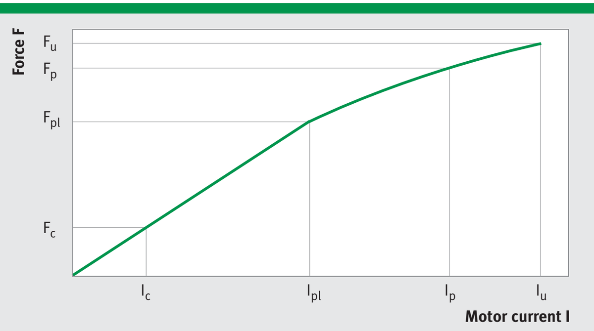
Force vs. current
Note:
The winding variant WM (standard) described above is suitable for moderately dynamic performance requirements. The winding variants WL and WH suitable for lower and higher dynamic performance requirements are available upon request. The integrated temperature sensors do not display the exact winding temperature. Depending on current load, the winding temperature may be up to approx. 30 K higher.
33
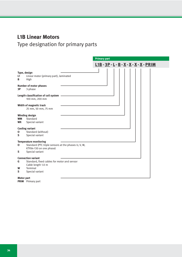
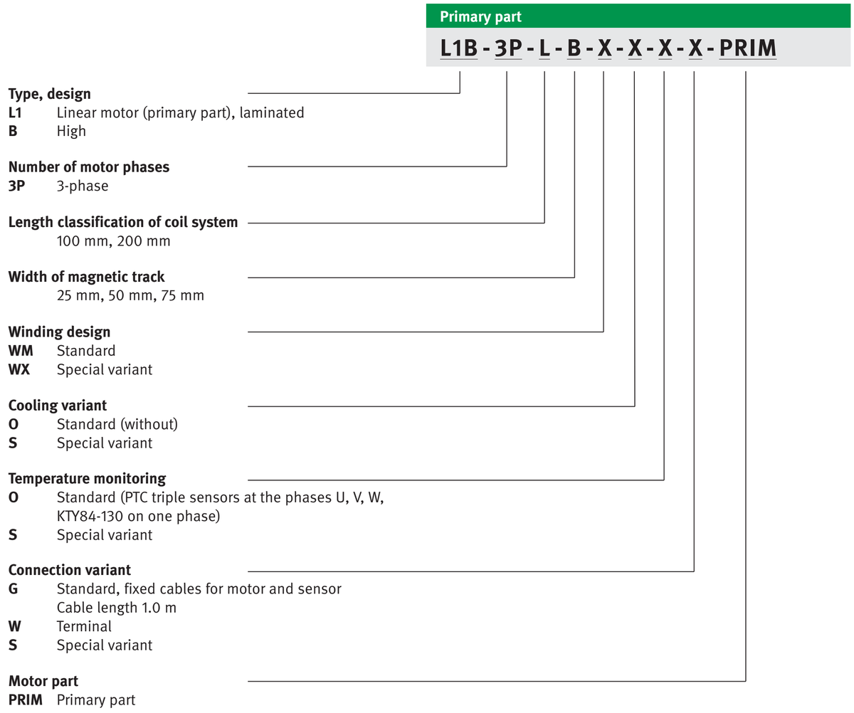
L1B Linear Motors
Type designation for primary parts
34
L1 Linear motor (primary part), laminated
B High
Number of motor phases
3P 3-phase
Length classification of coil system
100 mm, 200 mm
Width of magnetic track
25 mm, 50 mm, 75 mm
Winding design
WM Standard
WX Special variant
Cooling variant
O Standard (without)
S Special variant
Temperature monitoring
O Standard (PTC triple sensors at the phases U, V, W,
KTY84-130 on one phase)
S Special variant
Connection variant
G Standard, fixed cables for motor and sensor
Cable length 1.0 m
W Terminal
S Special variant
Motor part
PRIM Primary part
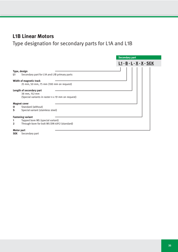
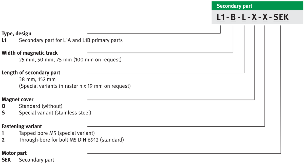
L1B Linear Motors
Type designation for secondary parts for L1A and L1B
同じ画像がページ 25 にも表示されています
35
L1 B L X X SEK
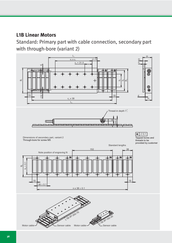
L1B Linear Motors
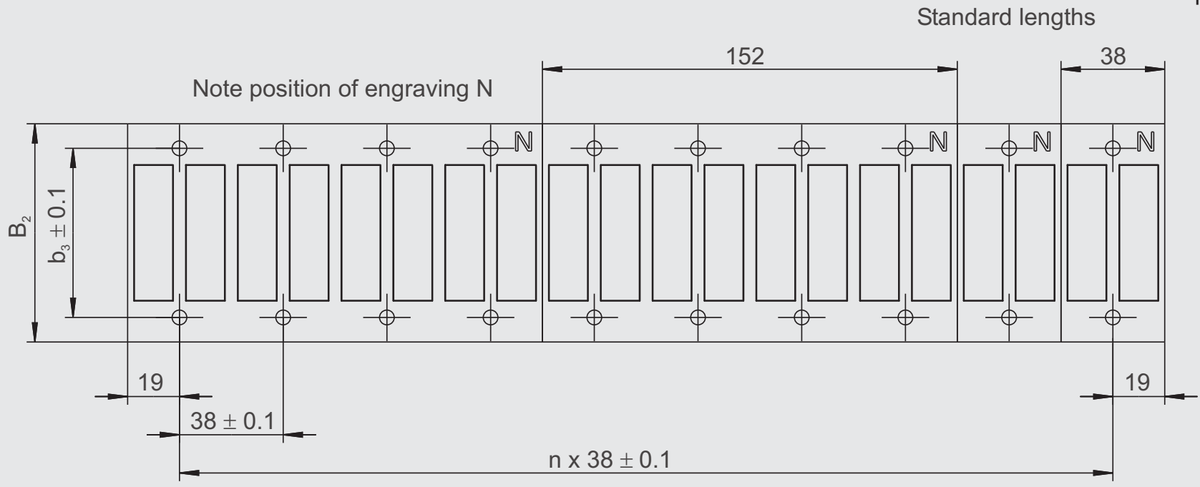
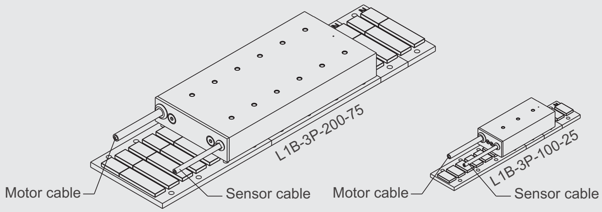
Standard: Primary part with cable connection, secondary part with through-bore (variant 2)
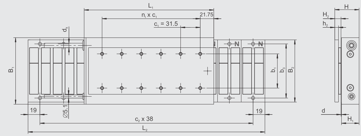
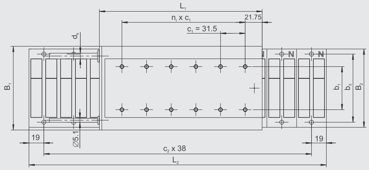
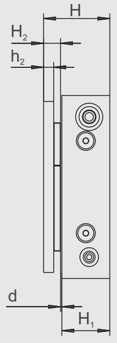

⊕ ∅ 0.1
Dimensions of secondary part, variant 2
Through-bore for screw M5
Tapped bores and
threads to be
provided by customer
36
L1B Linear Motors
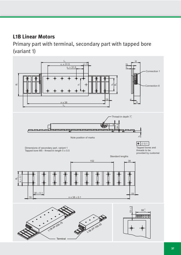
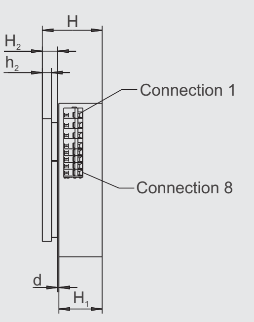
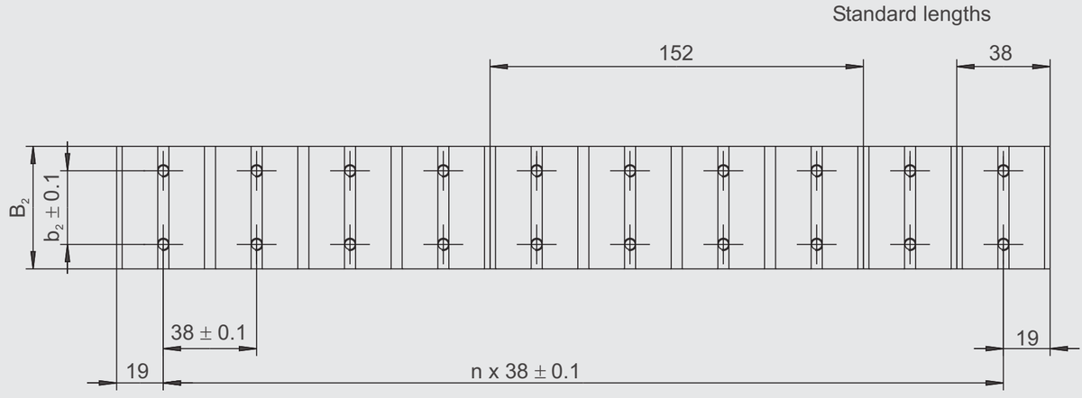
Primary part with terminal, secondary part with tapped bore (variant 1)
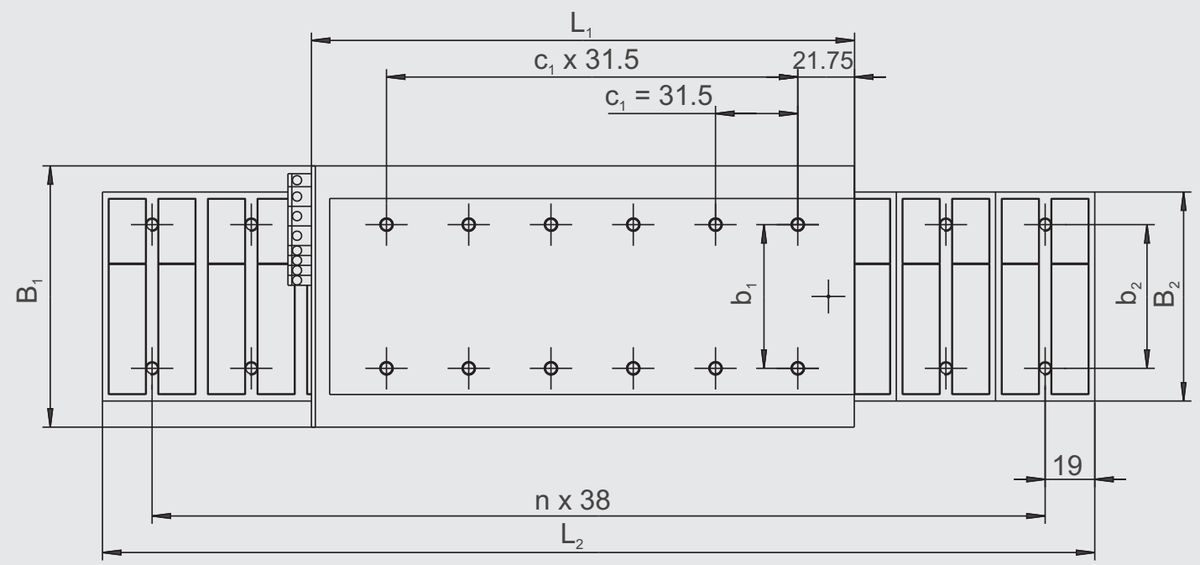
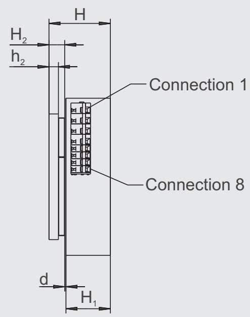

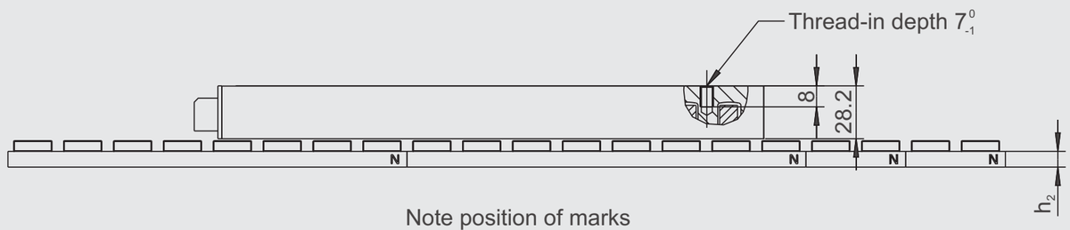
Dimensions of secondary part, variant 1
Tapped bore M5 - thread-in length 5 ± 0.5
Tapped bores and threads to be provided by customer
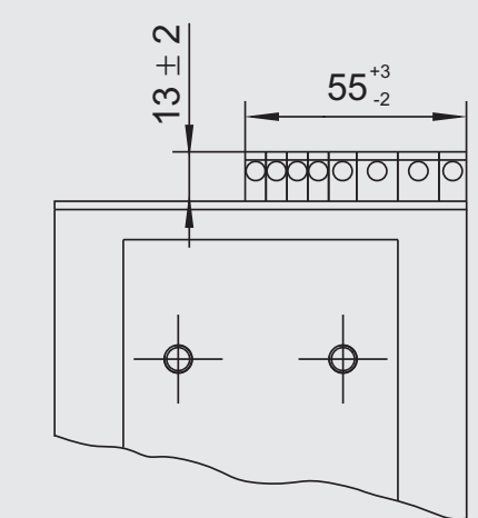
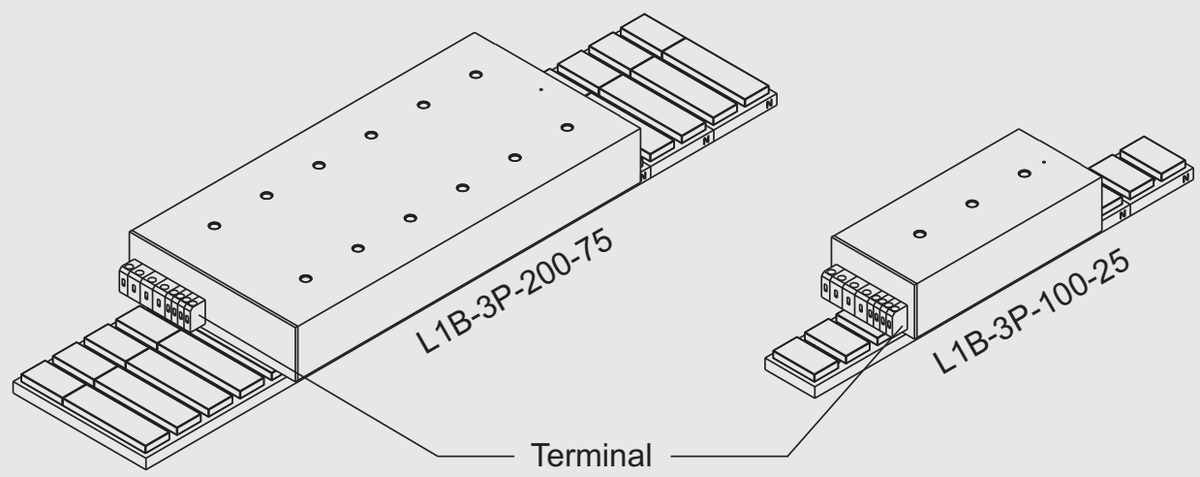
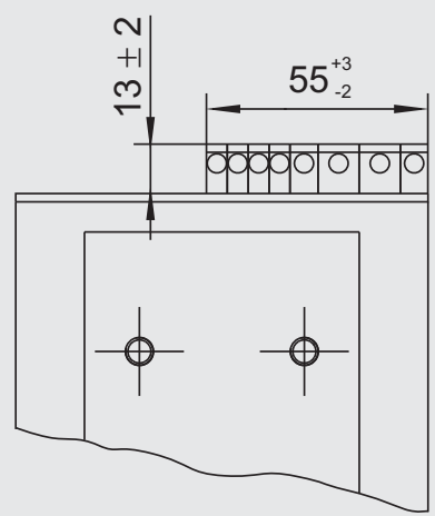
同じ画像がページ 27 にも表示されています
37
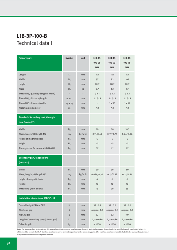
L1B-3P-100-B
Technical data I
| Primary part | Symbol | Unit | L1B-3P-100-25-WM | L1B-3P-100-50-WM | L1B-3P-100-75-WM |
|---|---|---|---|---|---|
| Length | L₁ | mm | 113 | 113 | 113 |
| Width | B₁ | mm | 57 | 82 | 107 |
| Height | H₁ | mm | 28.2 | 28.2 | 28.2 |
| Mass | m₁ | kg | 0.7 | 1.2 | 1.7 |
| Thread M5, quantity (length x width) | - | - | 3 x 1 | 3 x 2 | 3 x 2 |
| Thread M5, distance/length | n₁ x c₁ | mm | 2 x 31.5 | 2 x 31.5 | 2 x 31.5 |
| Thread M5, distance/width | n_b x b₁ | mm | - | 1 x 30 | 1 x 55 |
| Motor cable diameter | d_K | mm | 7.3 | 7.3 | 7.3 |
| Standard: Secondary part, through-bore (variant 2) | |||||
| Width | B₂ | mm | 50 | 80 | 100 |
| Mass, length 38/length 152 | m₂ | kg/unit | 0.11/0.44 | 0.19/0.76 | 0.24/0.96 |
| Height of magnetic base | h₂ | mm | 6 | 6 | 6 |
| Height | H₂ | mm | 10 | 10 | 10 |
| Through-bore for screw M5 DIN 6912 | b₃ | mm | 37 | 62 | 87 |
| Secondary part, tapped bore (variant 1) | |||||
| Width | B₂ | mm | 30 | 50 | 80 |
| Mass, length 38/length 152 | m₂ | kg/unit | 0.076/0.30 | 0.13/0.52 | 0.21/0.84 |
| Height of magnetic base | h₂ | mm | 6 | 6 | 6 |
| Height | H₂ | mm | 10 | 10 | 10 |
| Thread M5 (from below) | b₂ | mm | 15 | 30 | 55 |
| Thread M5 (from below) | b₂ | mm | 15 | 30 | 55 |
| Installation dimensions: L1B-3P-L-B | |||||
| Overall height PRIM + SEK | H | mm | 39 - 0.1 | 39 - 0.1 | 39 - 0.1 |
| Mech. air gap | d | mm | approx. 0.8 | approx. 0.8 | approx. 0.8 |
| Max. width | B | mm | 57 | 82 | 107 |
| Length of secondary part (38 mm grid) | L₂ | mm | L₁ + stroke | L₁ + stroke | L₁ + stroke |
| Cable length | L_K | mm | ≈ 1000 | ≈ 1000 | ≈ 1000 |
Note: The size specified for the air gap d is an auxiliary dimension and may fluctuate. The only technically relevant dimension is the specified overall installation height H, which must be complied with. A stainless steel cover can be ordered separately for the secondary parts. (The stainless steel cover is not included in the standard equipment.) Subject to modification without previous notice.
38
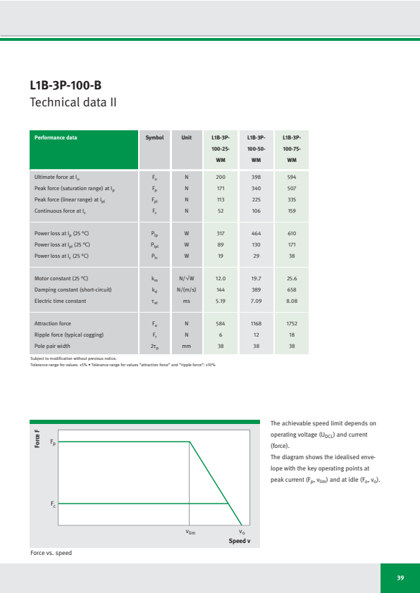
L1B-3P-100-B
Technical data II
| Performance data | Symbol | Unit | L1B-3P- 100-25- WM | L1B-3P- 100-50- WM | L1B-3P- 100-75- WM |
|---|---|---|---|---|---|
| Ultimate force at Iu | Fu | N | 200 | 398 | 594 |
| Peak force (saturation range) at Ip | Fp | N | 171 | 340 | 507 |
| Peak force (linear range) at Ipl | Fpl | N | 113 | 225 | 335 |
| Continuous force at Ic | Fc | N | 52 | 106 | 159 |
| Power loss at Ip (25 °C) | Plp | W | 317 | 464 | 610 |
| Power loss at Ipl (25 °C) | Plpl | W | 89 | 130 | 171 |
| Power loss at Ic (25 °C) | Plc | W | 19 | 29 | 38 |
| Motor constant (25 °C) | km | N/√W | 12.0 | 19.7 | 25.6 |
| Damping constant (short-circuit) | kd | N/(m/s) | 144 | 389 | 658 |
| Electric time constant | τel | ms | 5.19 | 7.09 | 8.08 |
| Attraction force | Fa | N | 584 | 1168 | 1752 |
| Ripple force (typical cogging) | Fr | N | 6 | 12 | 18 |
| Pole pair width | 2τp | mm | 38 | 38 | 38 |
Subject to modification without previous notice.
Tolerance range for values: ±5% • Tolerance range for values “attraction force” and “ripple force”: ±10%
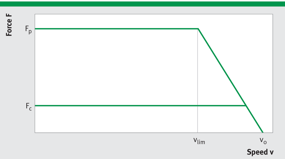
Force vs. speed
The achievable speed limit depends on operating voltage (U_DCL) and current (force).
The diagram shows the idealised envelope with the key operating points at peak current (Fₚ, vₗᵢₘ) and at idle (Fₒ, vₒ).
39
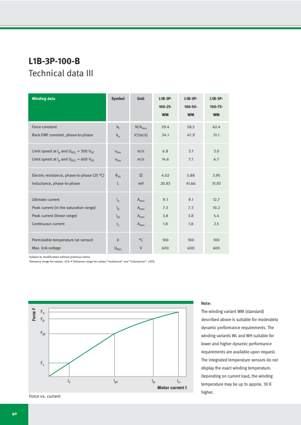
L1B-3P-100-B
Technical data III
| Winding data | Symbol | Unit | L1B-3P-100-25-WM | L1B-3P-100-50-WM | L1B-3P-100-75-WM |
|---|---|---|---|---|---|
| Force constant | kf | N/Arms | 29.4 | 58.5 | 62.4 |
| Back EMF constant, phase-to-phase | ku | V/(m/s) | 24.1 | 47.9 | 51.1 |
| Limit speed at Ip and UDCL = 300 VDC | vlim | m/s | 6.8 | 3.1 | 3.0 |
| Limit speed at Ip and UDCL = 600 VDC | vlim | m/s | 14.6 | 7.1 | 6.7 |
| Electric resistance, phase-to-phase (25 °C) | R25 | Ω | 4.02 | 5.88 | 3.95 |
| Inductance, phase-to-phase | L | mH | 20.83 | 41.66 | 31.92 |
| Ultimate current | Iu | Arms | 9.1 | 9.1 | 12.7 |
| Peak current (in the saturation range) | Ip | Arms | 7.3 | 7.3 | 10.2 |
| Peak current (linear range) | Ipl | Arms | 3.8 | 3.8 | 5.4 |
| Continuous current | Ic | Arms | 1.8 | 1.8 | 2.5 |
| Permissible temperature (at sensor) | ϑ | °C | 100 | 100 | 100 |
| Max. link voltage | UDCL | V | 600 | 600 | 600 |
Subject to modification without previous notice.
Tolerance range for values: ±5% • Tolerance range for values "resistance" and "inductance": ±10%
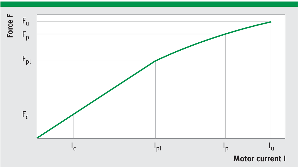
Force vs. current
Note:
The winding variant WM (standard) described above is suitable for moderately dynamic performance requirements. The winding variants WL and WH suitable for lower and higher dynamic performance requirements are available upon request. The integrated temperature sensors do not display the exact winding temperature. Depending on current load, the winding temperature may be up to approx. 30 K higher.
40
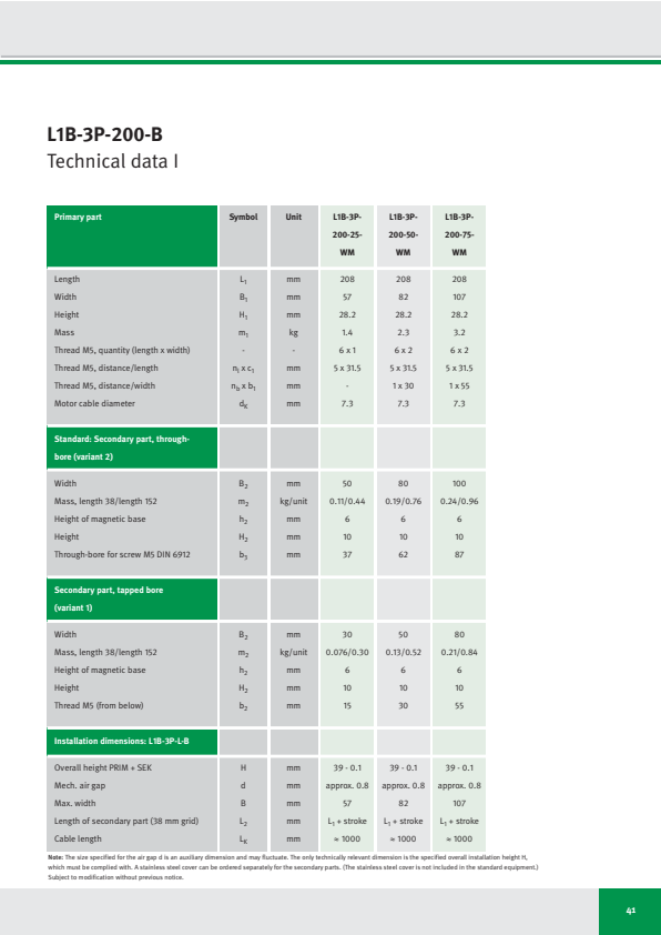
L1B-3P-200-B
Technical data I
| Primary part | Symbol | Unit | L1B-3P-200-25-WM | L1B-3P-200-50-WM | L1B-3P-200-75-WM |
|---|---|---|---|---|---|
| Length | L₁ | mm | 208 | 208 | 208 |
| Width | B₁ | mm | 57 | 82 | 107 |
| Height | H₁ | mm | 28.2 | 28.2 | 28.2 |
| Mass | m₁ | kg | 1.4 | 2.3 | 3.2 |
| Thread M5, quantity (length x width) | - | - | 6 x 1 | 6 x 2 | 6 x 2 |
| Thread M5, distance/length | n₁ x c₁ | mm | 5 x 31.5 | 5 x 31.5 | 5 x 31.5 |
| Thread M5, distance/width | n_b x b₁ | mm | - | 1 x 30 | 1 x 55 |
| Motor cable diameter | d_K | mm | 7.3 | 7.3 | 7.3 |
| Standard: Secondary part, through-bore (variant 2) | |||||
| Width | B₂ | mm | 50 | 80 | 100 |
| Mass, length 38/length 152 | m₂ | kg/unit | 0.11/0.44 | 0.19/0.76 | 0.24/0.96 |
| Height of magnetic base | h₂ | mm | 6 | 6 | 6 |
| Height | H₂ | mm | 10 | 10 | 10 |
| Through-bore for screw M5 DIN 6912 | b₃ | mm | 37 | 62 | 87 |
| Secondary part, tapped bore (variant 1) | |||||
| Width | B₂ | mm | 30 | 50 | 80 |
| Mass, length 38/length 152 | m₂ | kg/unit | 0.076/0.30 | 0.13/0.52 | 0.21/0.84 |
| Height of magnetic base | h₂ | mm | 6 | 6 | 6 |
| Height | H₂ | mm | 10 | 10 | 10 |
| Thread M5 (from below) | b₂ | mm | 15 | 30 | 55 |
| Thread M5 (from below) | b₂ | mm | 15 | 30 | 55 |
| Installation dimensions: L1B-3P-L-B | |||||
| Overall height PRIM + SEK | H | mm | 39 - 0.1 | 39 - 0.1 | 39 - 0.1 |
| Mech. air gap | d | mm | approx. 0.8 | approx. 0.8 | approx. 0.8 |
| Max. width | B | mm | 57 | 82 | 107 |
| Length of secondary part (38 mm grid) | L₂ | mm | L₁ + stroke | L₁ + stroke | L₁ + stroke |
| Cable length | L_K | mm | ≈ 1000 | ≈ 1000 | ≈ 1000 |
Note: The size specified for the air gap d is an auxiliary dimension and may fluctuate. The only technically relevant dimension is the specified overall installation height H, which must be complied with. A stainless steel cover can be ordered separately for the secondary parts. (The stainless steel cover is not included in the standard equipment.) Subject to modification without previous notice.
41
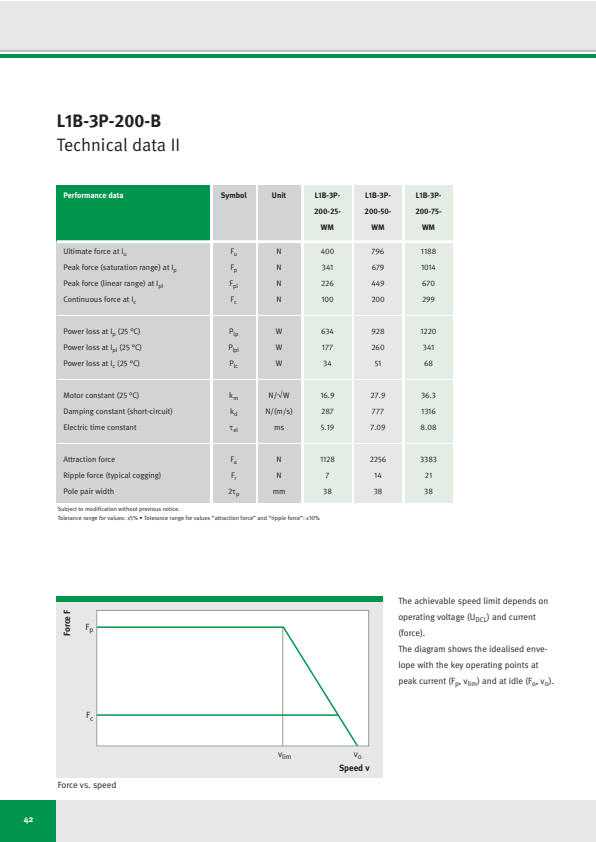
L1B-3P-200-B
Technical data II
| Performance data | Symbol | Unit | L1B-3P- 200-25- WM | L1B-3P- 200-50- WM | L1B-3P- 200-75- WM |
|---|---|---|---|---|---|
| Ultimate force at Iu | Fu | N | 400 | 796 | 1188 |
| Peak force (saturation range) at Ip | Fp | N | 341 | 679 | 1014 |
| Peak force (linear range) at Ipl | Fpl | N | 226 | 449 | 670 |
| Continuous force at Ic | Fc | N | 100 | 200 | 299 |
| Power loss at Ip (25 °C) | Plp | W | 634 | 928 | 1220 |
| Power loss at Ipl (25 °C) | Plpl | W | 177 | 260 | 341 |
| Power loss at Ic (25 °C) | Plc | W | 34 | 51 | 68 |
| Motor constant (25 °C) | km | N/√W | 16.9 | 27.9 | 36.3 |
| Damping constant (short-circuit) | kd | N/(m/s) | 287 | 777 | 1316 |
| Electric time constant | τel | ms | 5.19 | 7.09 | 8.08 |
| Attraction force | Fa | N | 1128 | 2256 | 3383 |
| Ripple force (typical cogging) | Fr | N | 7 | 14 | 21 |
| Pole pair width | 2τp | mm | 38 | 38 | 38 |
Subject to modification without previous notice.
Tolerance range for values: ±5% • Tolerance range for values “attraction force” and “ripple force”: ±10%
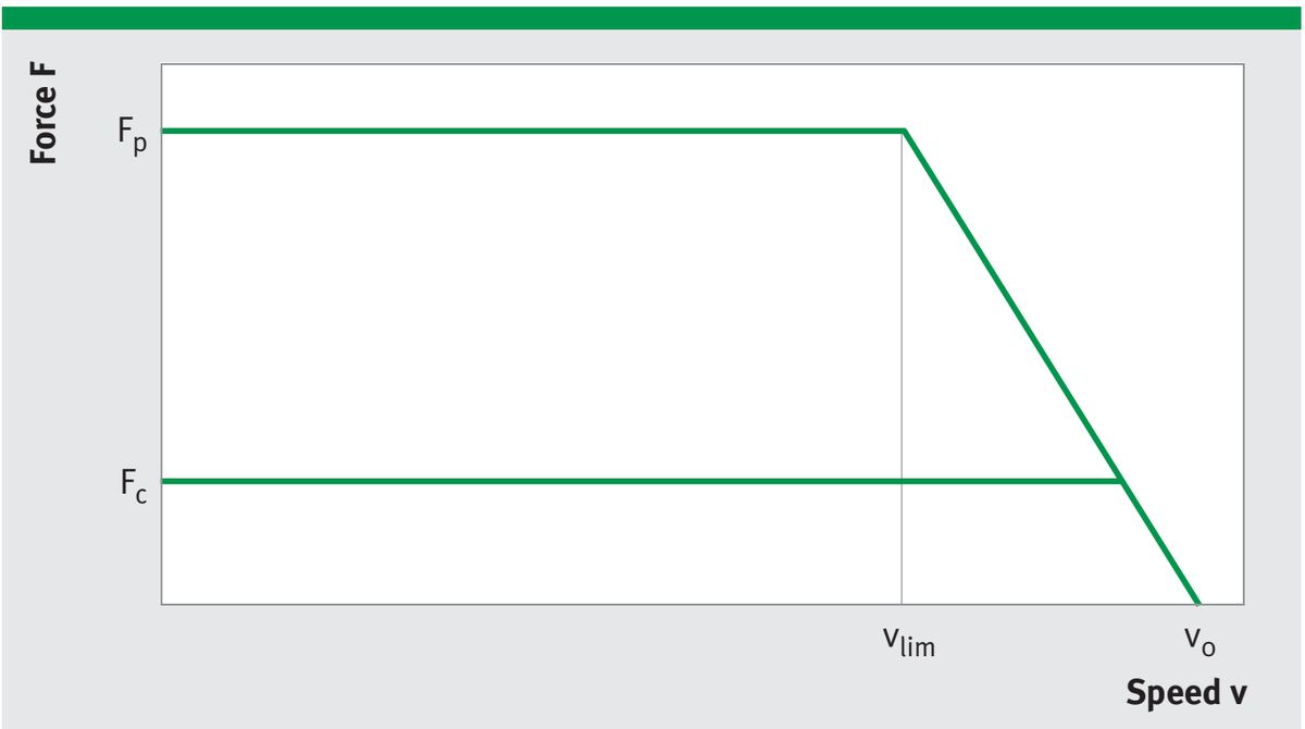
Force vs. speed
The achievable speed limit depends on operating voltage (U_DCL) and current (force).
The diagram shows the idealised envelope with the key operating points at peak current (Fₚ, vₗᵢₘ) and at idle (Fₒ, vₒ).
42
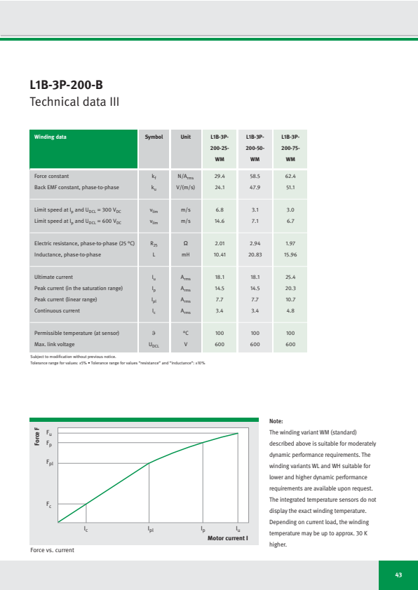
L1B-3P-200-B
Technical data III
| Winding data | Symbol | Unit | L1B-3P-200-25-WM | L1B-3P-200-50-WM | L1B-3P-200-75-WM |
|---|---|---|---|---|---|
| Force constant | k_f | N/A_rms | 29.4 | 58.5 | 62.4 |
| Back EMF constant, phase-to-phase | k_u | V/(m/s) | 24.1 | 47.9 | 51.1 |
| Limit speed at I_p and U_DCL = 300 V_DC | v_lim | m/s | 6.8 | 3.1 | 3.0 |
| Limit speed at I_p and U_DCL = 600 V_DC | v_lim | m/s | 14.6 | 7.1 | 6.7 |
| Electric resistance, phase-to-phase (25 °C) | R_25 | Ω | 2.01 | 2.94 | 1.97 |
| Inductance, phase-to-phase | L | mH | 10.41 | 20.83 | 15.96 |
| Ultimate current | I_u | A_rms | 18.1 | 18.1 | 25.4 |
| Peak current (in the saturation range) | I_p | A_rms | 14.5 | 14.5 | 20.3 |
| Peak current (linear range) | I_pl | A_rms | 7.7 | 7.7 | 10.7 |
| Continuous current | I_c | A_rms | 3.4 | 3.4 | 4.8 |
| Permissible temperature (at sensor) | ϑ | °C | 100 | 100 | 100 |
| Max. link voltage | U_DCL | V | 600 | 600 | 600 |
Subject to modification without previous notice.
Tolerance range for values: ±5% • Tolerance range for values “resistance” and “inductance”: ±10%
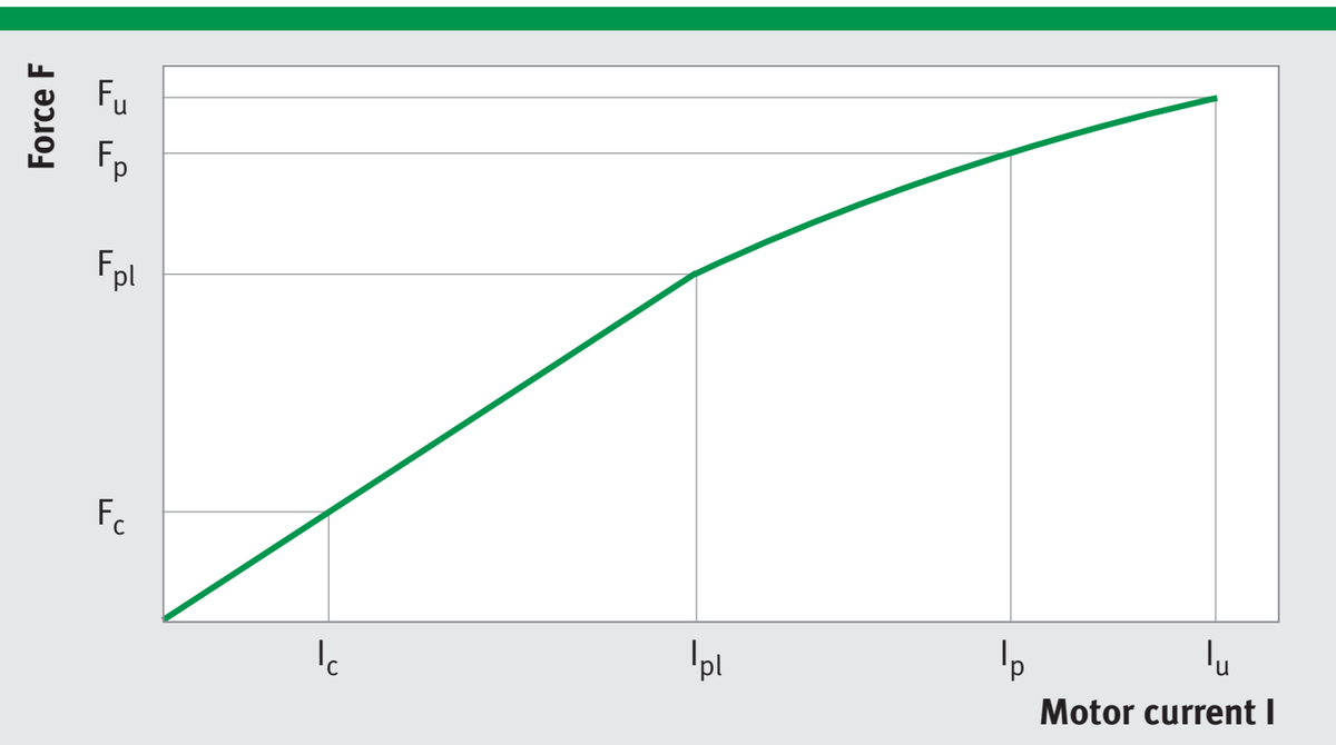
Force vs. current
Note:
The winding variant WM (standard) described above is suitable for moderately dynamic performance requirements. The winding variants WL and WH suitable for lower and higher dynamic performance requirements are available upon request. The integrated temperature sensors do not display the exact winding temperature. Depending on current load, the winding temperature may be up to approx. 30 K higher.
43
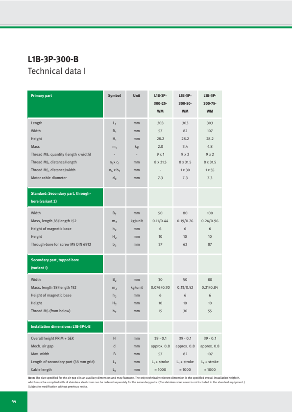
L1B-3P-300-B
Technical data I
| Primary part | Symbol | Unit | L1B-3P- 300-25- WM | L1B-3P- 300-50- WM | L1B-3P- 300-75- WM |
|---|---|---|---|---|---|
| Length | L1 | mm | 303 | 303 | 303 |
| Width | B1 | mm | 57 | 82 | 107 |
| Height | H1 | mm | 28.2 | 28.2 | 28.2 |
| Mass | m1 | kg | 2.0 | 3.4 | 4.8 |
| Thread M5, quantity (length x width) | - | - | 9 x 1 | 9 x 2 | 9 x 2 |
| Thread M5, distance/length | nl x c1 | mm | 8 x 31.5 | 8 x 31.5 | 8 x 31.5 |
| Thread M5, distance/width | nb x b1 | mm | - | 1 x 30 | 1 x 55 |
| Motor cable diameter | dK | mm | 7.3 | 7.3 | 7.3 |
| Standard: Secondary part, through- bore (variant 2) | |||||
| Width | B2 | mm | 50 | 80 | 100 |
| Mass, length 38/length 152 | m2 | kg/unit | 0.11/0.44 | 0.19/0.76 | 0.24/0.96 |
| Height of magnetic base | h2 | mm | 6 | 6 | 6 |
| Height | H2 | mm | 10 | 10 | 10 |
| Through-bore for screw M5 DIN 6912 | b3 | mm | 37 | 62 | 87 |
| Secondary part, tapped bore (variant 1) | |||||
| Width | B2 | mm | 30 | 50 | 80 |
| Mass, length 38/length 152 | m2 | kg/unit | 0.076/0.30 | 0.13/0.52 | 0.21/0.84 |
| Height of magnetic base | h2 | mm | 6 | 6 | 6 |
| Height | H2 | mm | 10 | 10 | 10 |
| Thread M5 (from below) | b2 | mm | 15 | 30 | 55 |
| Installation dimensions: L1B-3P-L-B | |||||
| Overall height PRIM + SEK | H | mm | 39 - 0.1 | 39 - 0.1 | 39 - 0.1 |
| Mech. air gap | d | mm | approx. 0.8 | approx. 0.8 | approx. 0.8 |
| Max. width | B | mm | 57 | 82 | 107 |
| Length of secondary part (38 mm grid) | L2 | mm | L1 + stroke | L1 + stroke | L1 + stroke |
| Cable length | LK | mm | ≈ 1000 | ≈ 1000 | ≈ 1000 |
Note: The size specified for the air gap d is an auxiliary dimension and may fluctuate. The only technically relevant dimension is the specified overall installation height H, which must be complied with. A stainless steel cover can be ordered separately for the secondary parts. (The stainless steel cover is not included in the standard equipment.) Subject to modification without previous notice.
44
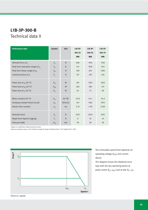
L1B-3P-300-B
Technical data II
| Performance data | Symbol | Unit | L1B-3P-300-25-WM | L1B-3P-300-50-WM | L1B-3P-300-75-WM |
|---|---|---|---|---|---|
| Ultimate force at Iu | Fu | N | 600 | 1194 | 1782 |
| Peak force (saturation range) at Ip | Fp | N | 512 | 1019 | 1521 |
| Peak force (linear range) at Ipl | Fpl | N | 339 | 674 | 1005 |
| Continuous force at Ic | Fc | N | 147 | 292 | 436 |
| Power loss at Ip (25 °C) | Plp | W | 951 | 1392 | 1832 |
| Power loss at Ipl (25 °C) | Plpl | W | 266 | 389 | 512 |
| Power loss at Ic (25 °C) | Plc | W | 50 | 73 | 96 |
| Motor constant (25 °C) | km | N/√W | 20.8 | 34.1 | 44.4 |
| Damping constant (short-circuit) | kd | N/(m/s) | 431 | 1166 | 1972 |
| Electric time constant | τel | ms | 5.19 | 7.09 | 8.08 |
| Attraction force | Fa | N | 1672 | 3343 | 5015 |
| Ripple force (typical cogging) | Fr | N | 8 | 16 | 24 |
| Pole pair width | 2τp | mm | 38 | 38 | 38 |
Subject to modification without previous notice.
Tolerance range for values: ±5% • Tolerance range for values “attraction force” and “ripple force”: ±10%
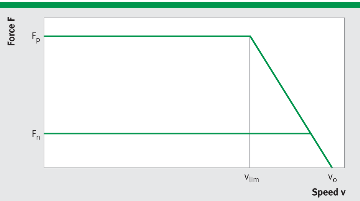
Force vs. speed
The achievable speed limit depends on operating voltage (U_zk) and current (force).
The diagram shows the idealised envelope with the key operating points at peak current (Fₚ, vₗᵢₘ) and at idle (Fₒ, vₒ).
45
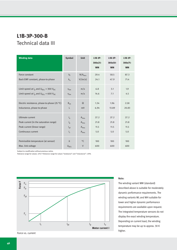
L1B-3P-300-B
Technical data III
| Winding data | Symbol | Unit | L1B-3P-300x25-WM | L1B-3P-300x50-WM | L1B-3P-300x75-WM |
|---|---|---|---|---|---|
| Force constant | kf | N/Arms | 29.4 | 58.5 | 87.3 |
| Back EMF constant, phase-to-phase | ku | V/(m/s) | 24.1 | 47.9 | 71.4 |
| Limit speed at Ip and UDCL = 300 VDC | vlim | m/s | 6.8 | 3.1 | 1.9 |
| Limit speed at Ip and UDCL = 600 VDC | vlim | m/s | 14.6 | 7.1 | 4.5 |
| Electric resistance, phase-to-phase (25 °C) | R25 | Ω | 1.34 | 1.96 | 2.58 |
| Inductance, phase-to-phase | L | mH | 6.94 | 13.89 | 20.83 |
| Ultimate current | Iu | Arms | 27.2 | 27.2 | 27.2 |
| Peak current (in the saturation range) | Ip | Arms | 21.8 | 21.8 | 21.8 |
| Peak current (linear range) | Ipl | Arms | 11.5 | 11.5 | 11.5 |
| Continuous current | Ic | Arms | 5.0 | 5.0 | 5.0 |
| Permissible temperature (at sensor) | ϑ | °C | 100 | 100 | 100 |
| Max. link voltage | UDCL | V | 600 | 600 | 600 |
Subject to modification without previous notice.
Tolerance range for values: ±5% • Tolerance range for values "resistance" and "inductance": ±10%
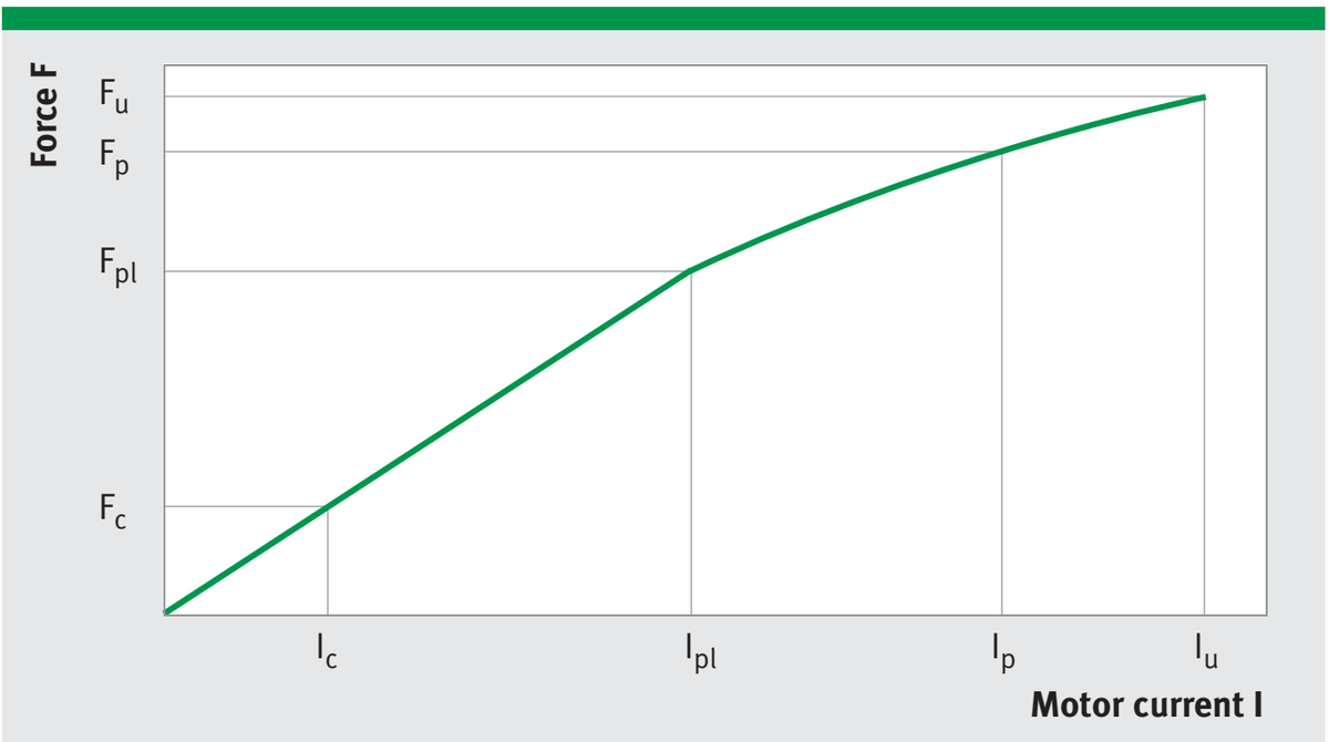
Force vs. current
Note:
The winding variant WM (standard) described above is suitable for moderately dynamic performance requirements. The winding variants WL and WH suitable for lower and higher dynamic performance requirements are available upon request. The integrated temperature sensors do not display the exact winding temperature. Depending on current load, the winding temperature may be up to approx. 30 K higher.
46
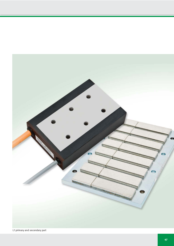
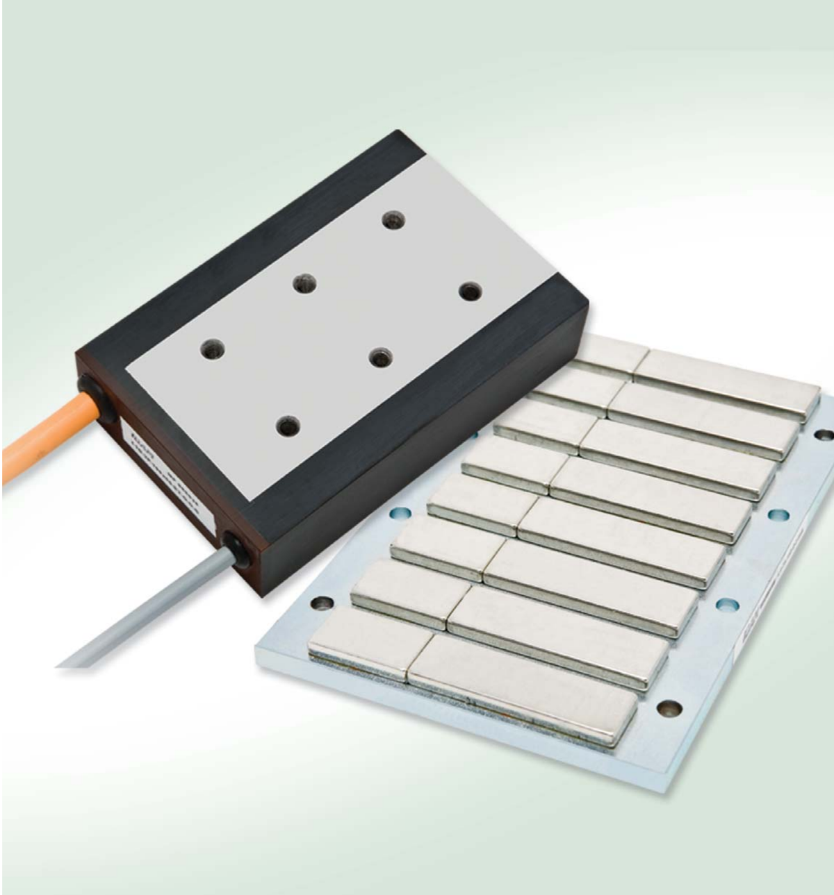
L1 primary and secondary part
47
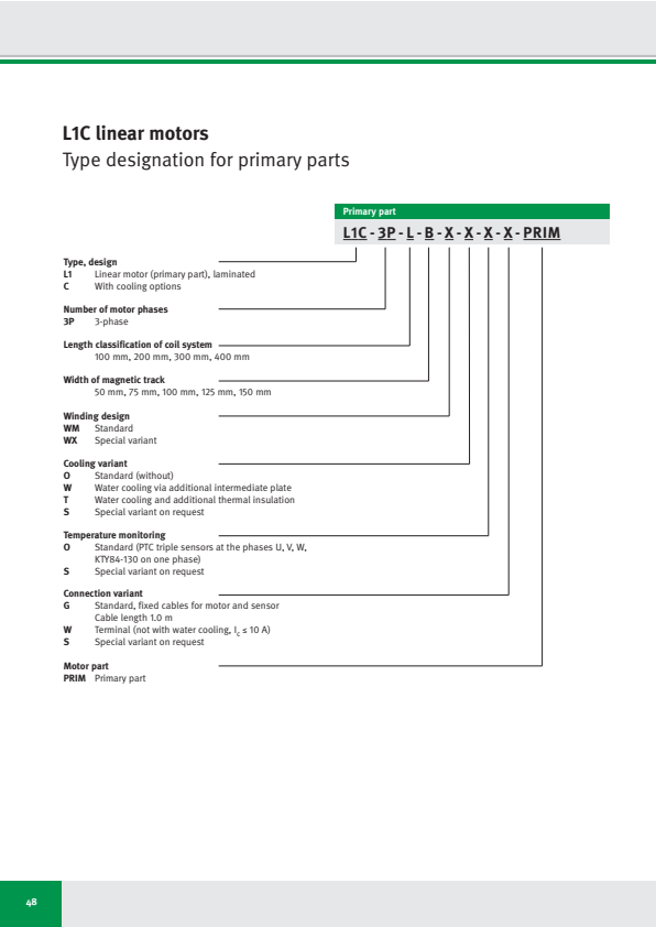
L1C linear motors
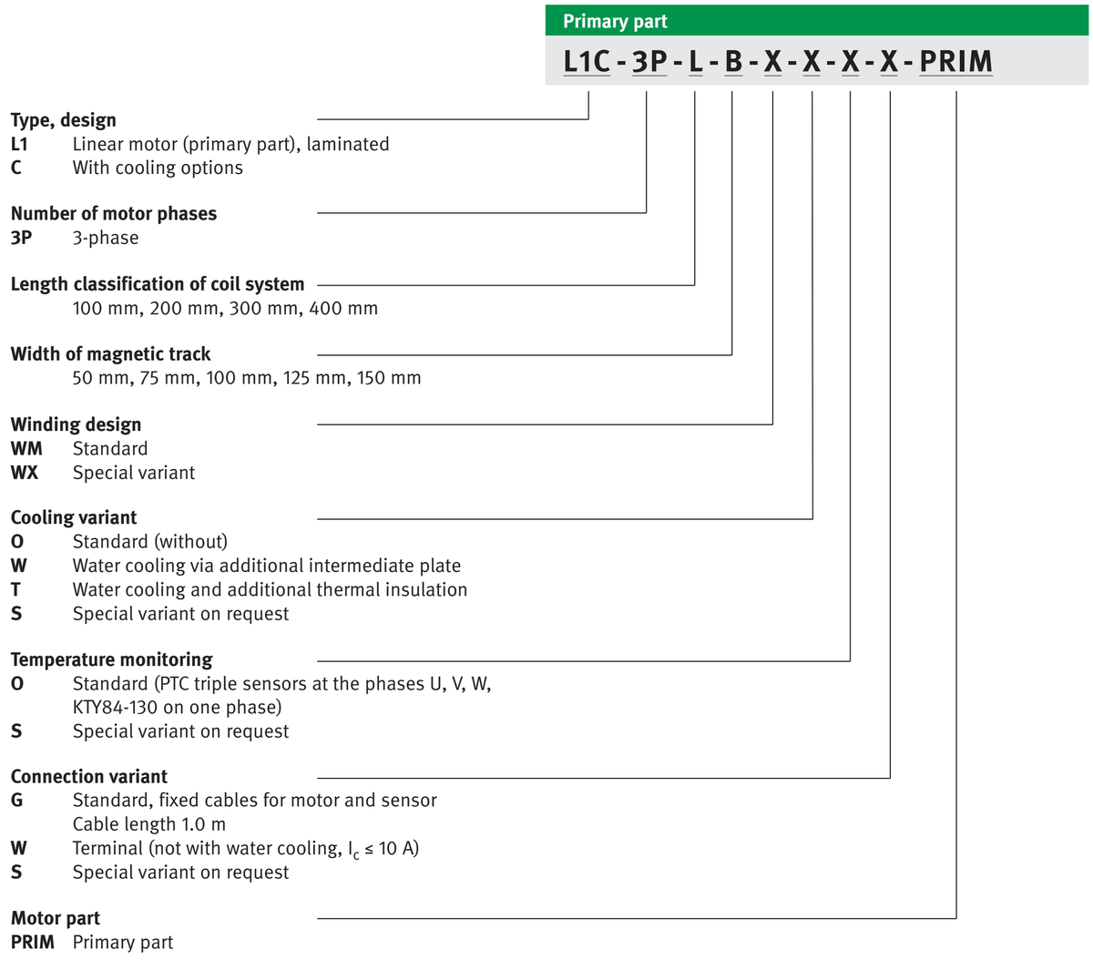
Type designation for primary parts
48
L1C - 3P - L - B - X - X - X - X - PRIM L1C - 3P - L - B - X - X - X - X - PRIM L1C - 3P - L - B - X - X - X - X - PRIM
Type, design Type, design Type, design
L1 Linear motor (primary part), laminated
C With cooling options
Number of motor phases Number of motor phases Number of motor phases
3P 3-phase
Length classification of coil system Length classification of coil system Length classification of coil system
100 mm, 200 mm, 300 mm, 400 mm
Width of magnetic track Width of magnetic track Width of magnetic track
50 mm, 75 mm, 100 mm, 125 mm, 150 mm
Winding design Winding design Winding design
WM Standard
WX Special variant
Cooling variant Cooling variant Cooling variant
O Standard (without)
W Water cooling via additional intermediate plate
T Water cooling and additional thermal insulation
S Special variant on request
Temperature monitoring Temperature monitoring Temperature monitoring
O Standard (PTC triple sensors at the phases U, V, W, KTY84-130 on one phase)
S Special variant on request
Connection variant Connection variant Connection variant
G Standard, fixed cables for motor and sensor Cable length 1.0 m
W Terminal (not with water cooling, Ic ≤ 10 A)
S Special variant on request
Motor part Motor part Motor part
PRIM Primary part
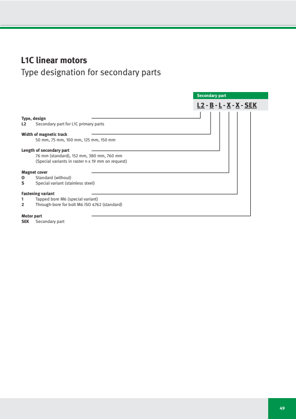
L1C linear motors
Type designation for secondary parts
| Secondary part | ||
|---|---|---|
| L2 - B - L - X - X - SEK | ||
| Type, design | L2 | Secondary part for L1C primary parts |
| Width of magnetic track | B | 50 mm, 75 mm, 100 mm, 125 mm, 150 mm |
| Length of secondary part | L | 76 mm (standard), 152 mm, 380 mm, 760 mm |
| (Special variants in raster n x 19 mm on request) | ||
| Magnet cover | O | Standard (without) |
| S | Special variant (stainless steel) | |
| Fastening variant | 1 | Tapped bore M6 (special variant) |
| 2 | Through-bore for bolt M6 ISO 4762 (standard) | |
| Motor part | SEK | Secondary part |
49
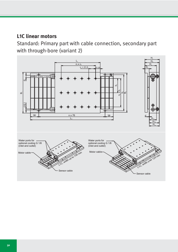
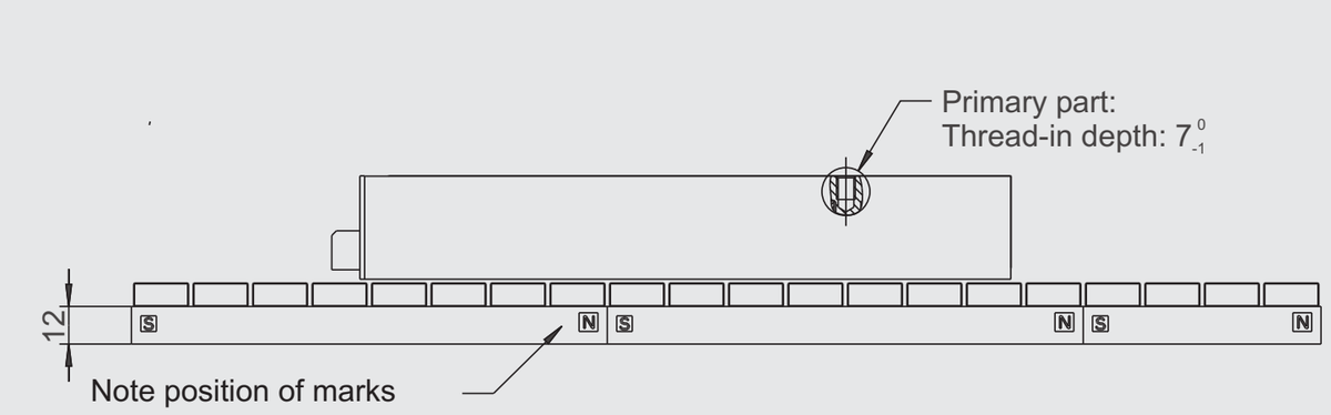
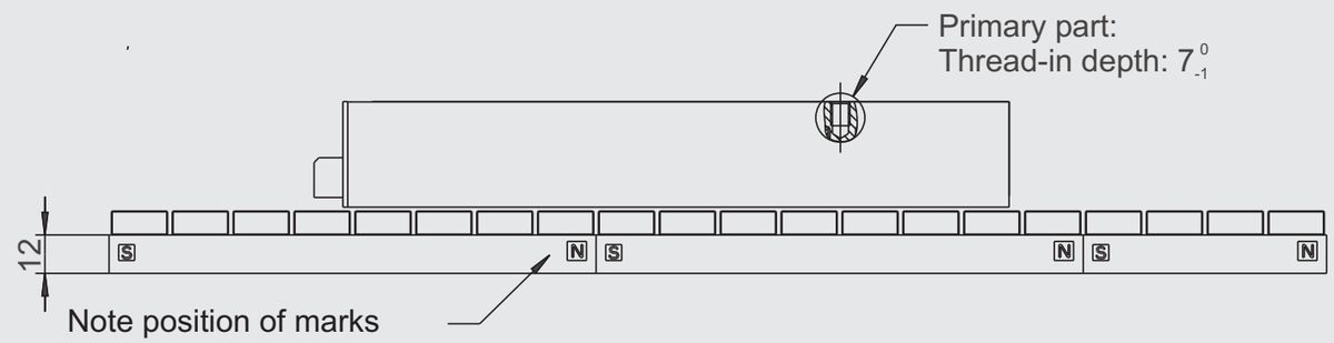
L1C linear motors
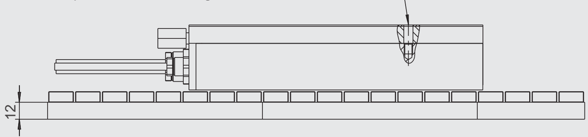
Standard: Primary part with cable connection, secondary part with through-bore (variant 2)
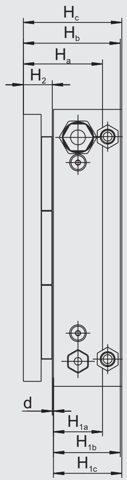
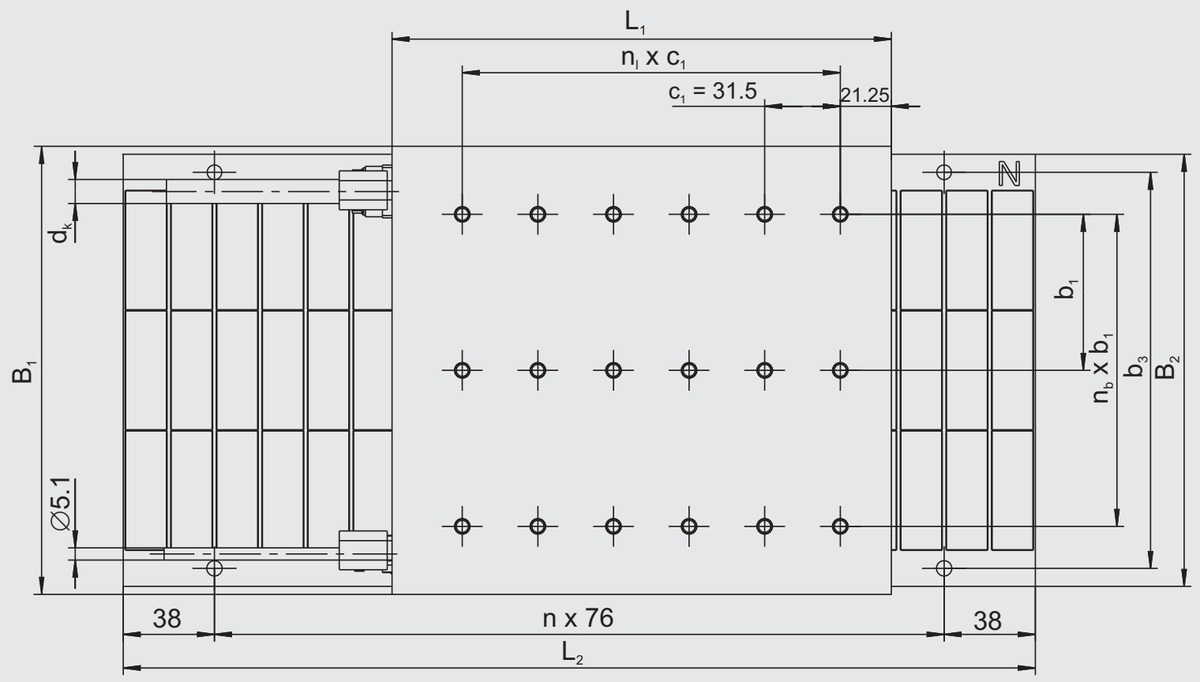
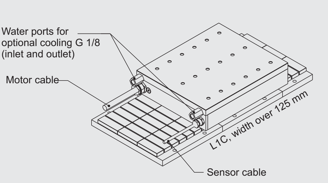
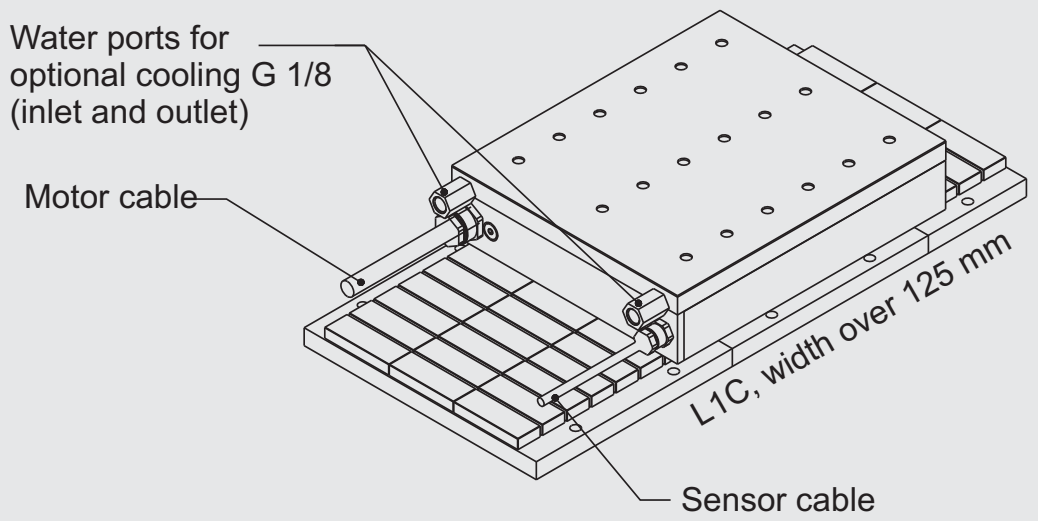
50
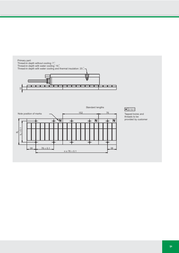
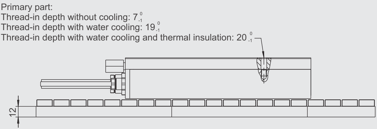
Primary part:
Thread-in depth without cooling: 7°
Thread-in depth with water cooling: 19°
Thread-in depth with water cooling and thermal insulation: 20°
Standard lengths
⊕ ∅ 0.1
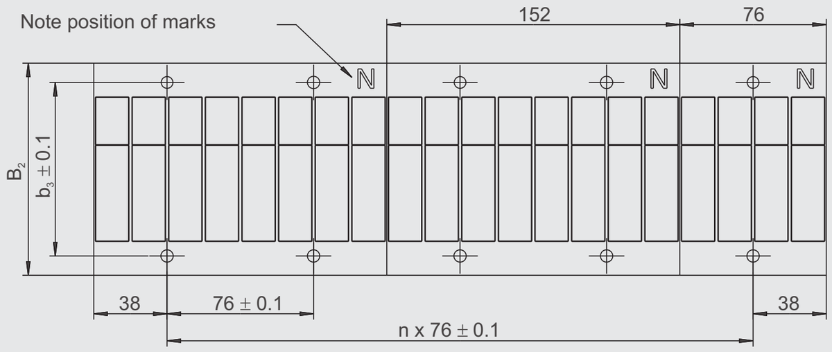
Tapped bores and
threads to be
provided by customer
51
⚠️ Another layout reading thinks this page has no table. We still deliver what was extracted (withholding data is harder to audit than delivering it), but please look at this one on the original page yourself — per-cell confidence says whether a value has a second reading, not whether this is really a table.
この表はこのページから抽出されましたが、正確な位置を特定できなかったため、ここ(末尾)に表示しています。
| ⊕ | ∅ 0.1 |
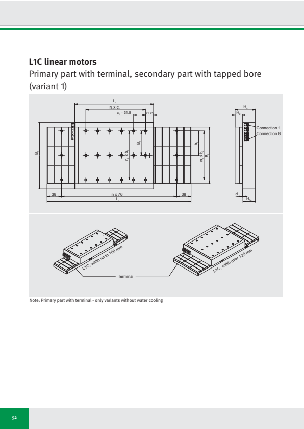
L1C linear motors
Primary part with terminal, secondary part with tapped bore (variant 1)
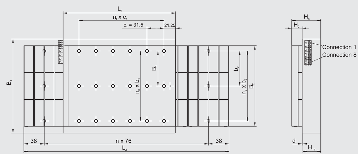
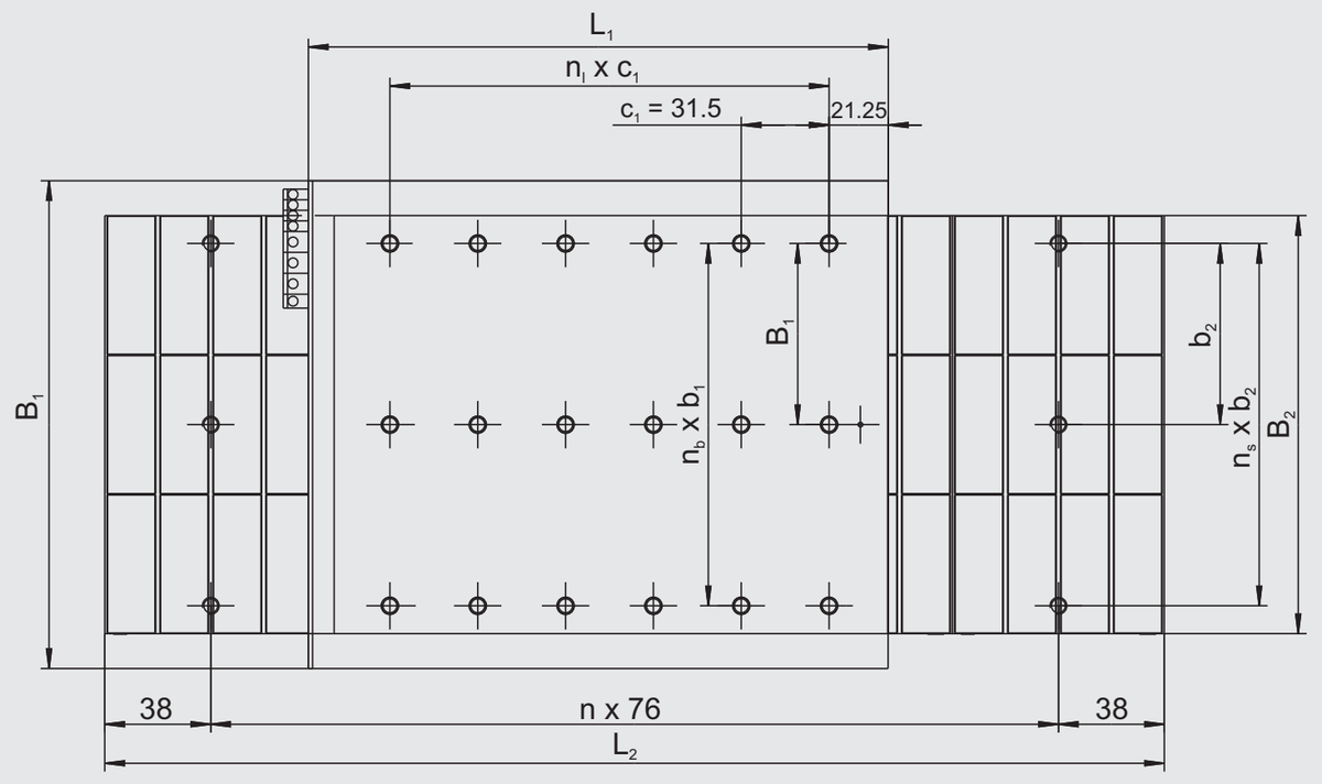
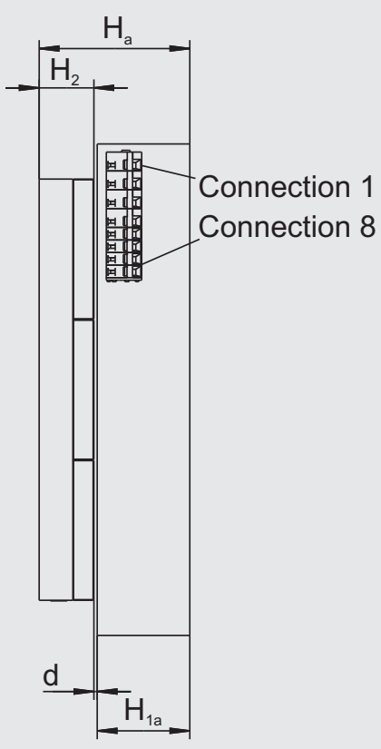
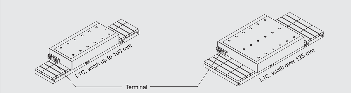
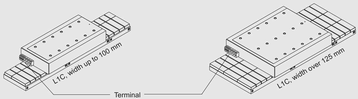
Note: Primary part with terminal - only variants without water cooling
52
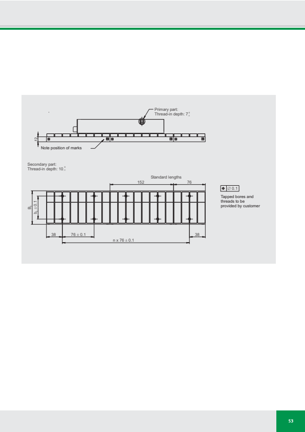
Secondary part:
Thread-in depth: 10³
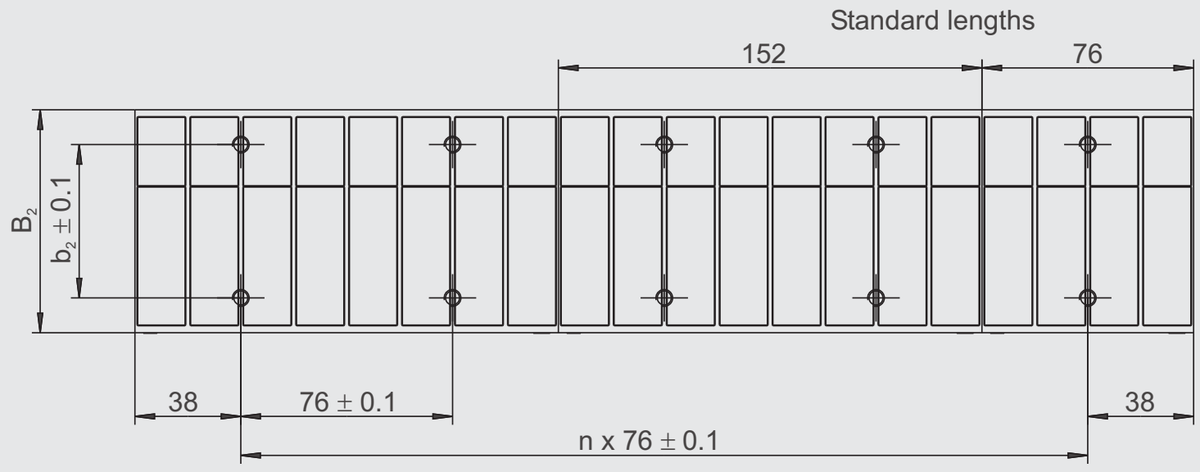
Tapped bores and
threads to be
provided by customer
53
⚠️ Another layout reading thinks this page has no table. We still deliver what was extracted (withholding data is harder to audit than delivering it), but please look at this one on the original page yourself — per-cell confidence says whether a value has a second reading, not whether this is really a table.
この表はこのページから抽出されましたが、正確な位置を特定できなかったため、ここ(末尾)に表示しています。
| ⊕ | ∅ 0.1 |
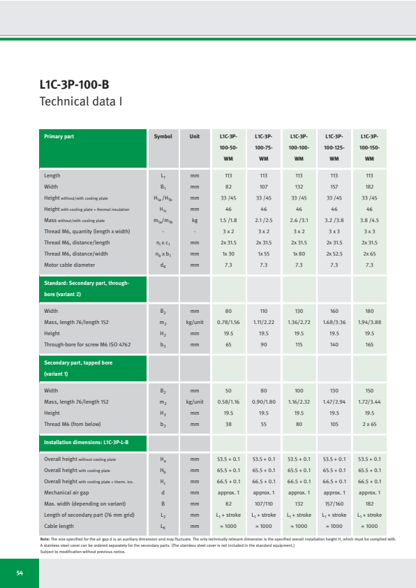
L1C-3P-100-B
Technical data I
| Primary part | Symbol | Unit | L1C-3P- 100-50- WM | L1C-3P- 100-75- WM | L1C-3P- 100-100- WM | L1C-3P- 100-125- WM | L1C-3P- 100-150- WM |
|---|---|---|---|---|---|---|---|
| Length | L1 | mm | 113 | 113 | 113 | 113 | 113 |
| Width | B1 | mm | 82 | 107 | 132 | 157 | 182 |
| Height without/with cooling plate | H1a /H1b | mm | 33 /45 | 33 /45 | 33 /45 | 33 /45 | 33 /45 |
| Height with cooling plate + thermal insulation | H1c | mm | 46 | 46 | 46 | 46 | 46 |
| Mass without/with cooling plate | m1a /m1b | kg | 1.5 /1.8 | 2.1 /2.5 | 2.6 /3.1 | 3.2 /3.8 | 3.8 /4.5 |
| Thread M6, quantity (length x width) | - | - | 3 x 2 | 3 x 2 | 3 x 2 | 3 x 3 | 3 x 3 |
| Thread M6, distance/length | nl x c1 | mm | 2x 31.5 | 2x 31.5 | 2x 31.5 | 2x 31.5 | 2x 31.5 |
| Thread M6, distance/width | nb x b1 | mm | 1x 30 | 1x 55 | 1x 80 | 2x 52.5 | 2x 65 |
| Motor cable diameter | dK | mm | 7.3 | 7.3 | 7.3 | 7.3 | 7.3 |
| Standard: Secondary part, through- bore (variant 2) | |||||||
| Width | B2 | mm | 80 | 110 | 130 | 160 | 180 |
| Mass, length 76/length 152 | m2 | kg/unit | 0.78/1.56 | 1.11/2.22 | 1.36/2.72 | 1.68/3.36 | 1.94/3.88 |
| Height | H2 | mm | 19.5 | 19.5 | 19.5 | 19.5 | 19.5 |
| Through-bore for screw M6 ISO 4762 | b3 | mm | 65 | 90 | 115 | 140 | 165 |
| Secondary part, tapped bore (variant 1) | |||||||
| Width | B2 | mm | 50 | 80 | 100 | 130 | 150 |
| Mass, length 76/length 152 | m2 | kg/unit | 0.58/1.16 | 0.90/1.80 | 1.16/2.32 | 1.47/2.94 | 1.72/3.44 |
| Height | H2 | mm | 19.5 | 19.5 | 19.5 | 19.5 | 19.5 |
| Thread M6 (from below) | b2 | mm | 38 | 55 | 80 | 105 | 2 x 65 |
| Installation dimensions: L1C-3P-L-B | |||||||
| Overall height without cooling plate | Ha | mm | 53.5 + 0.1 | 53.5 + 0.1 | 53.5 + 0.1 | 53.5 + 0.1 | 53.5 + 0.1 |
| Overall height with cooling plate | Hb | mm | 65.5 + 0.1 | 65.5 + 0.1 | 65.5 + 0.1 | 65.5 + 0.1 | 65.5 + 0.1 |
| Overall height with cooling plate + therm. ins. | Hc | mm | 66.5 + 0.1 | 66.5 + 0.1 | 66.5 + 0.1 | 66.5 + 0.1 | 66.5 + 0.1 |
| Mechanical air gap | d | mm | approx. 1 | approx. 1 | approx. 1 | approx. 1 | approx. 1 |
| Max. width (depending on variant) | B | mm | 82 | 107/110 | 132 | 157/160 | 182 |
| Length of secondary part (76 mm grid) | L2 | mm | L1 + stroke | L1 + stroke | L1 + stroke | L1 + stroke | L1 + stroke |
| Cable length | LK | mm | ≈ 1000 | ≈ 1000 | ≈ 1000 | ≈ 1000 | ≈ 1000 |
Note: The size specified for the air gap d is an auxiliary dimension and may fluctuate. The only technically relevant dimension is the specified overall installation height H, which must be complied with.
A stainless steel cover can be ordered separately for the secondary parts. (The stainless steel cover is not included in the standard equipment.)
Subject to modification without previous notice.
54
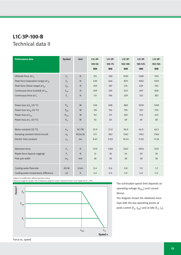
L1C-3P-100-B
Technical data II
| Performance data | Symbol | Unit | L1C-3P-100-50-WM | L1C-3P-100-75-WM | L1C-3P-100-100-WM | L1C-3P-100-125-WM | L1C-3P-100-150-WM |
|---|---|---|---|---|---|---|---|
| Ultimate force at Iu | Fu | N | 515 | 768 | 1020 | 1268 | 1515 |
| Peak force (saturation range) at Ip | Fp | N | 439 | 656 | 870 | 1082 | 1293 |
| Peak force (linear range) at Ipl | Fpl | N | 259 | 387 | 514 | 639 | 763 |
| Continuous force (cooled) at Icw | Fcw | N | 249 | 395 | 543 | 691 | 838 |
| Continuous force at Ic | Fc | N | 131 | 196 | 259 | 322 | 387 |
| Power loss at Ip (25 °C) | Plp | W | 528 | 698 | 869 | 1039 | 1209 |
| Power loss at Ipl (25 °C) | Plpl | W | 118 | 156 | 194 | 232 | 270 |
| Power loss at Icw | Plcw | W | 141 | 211 | 282 | 352 | 423 |
| Power loss at Ic (25 °C) | Plc | W | 30 | 40 | 49 | 59 | 69 |
| Motor constant (25 °C) | km | N/√W | 23.9 | 31.0 | 36.9 | 42.0 | 46.5 |
| Damping constant (short-circuit) | kd | N/(m/s) | 571 | 962 | 1362 | 1762 | 2160 |
| Electric time constant | τel | ms | 8.67 | 9.83 | 10.54 | 11.02 | 11.36 |
| Attraction force | Fa | N | 1174 | 1760 | 2347 | 2934 | 3521 |
| Ripple force (typical cogging) | Fr | N | 12 | 18 | 24 | 30 | 36 |
| Pole pair width | 2τp | mm | 38 | 38 | 38 | 38 | 38 |
| Cooling-water flow-rate | dV/dt | l/min | 0.4 | 0.6 | 0.8 | 1.0 | 1.2 |
| Cooling-water temperature-difference | Δϑ | K | 5.0 | 5.0 | 5.0 | 5.0 | 5.0 |
Subject to modification without previous notice.
Tolerance range for values: ±5% • Tolerance range for values “attraction force” and “ripple force”: ±10%
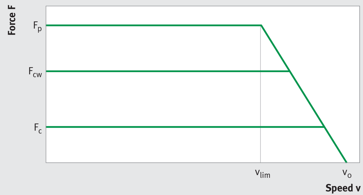
Force vs. speed
The achievable speed limit depends on operating voltage (U_DCL) and current (force).
The diagram shows the idealised envelope with the key operating points at peak current (Fₚ, vₗᵢₘ) and at idle (Fₒ, vₒ).
55
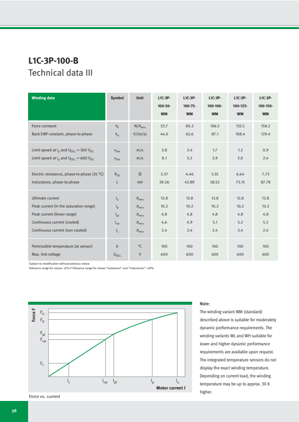
L1C-3P-100-B
Technical data III
| Winding data | Symbol | Unit | L1C-3P-100-50-WM | L1C-3P-100-75-WM | L1C-3P-100-100-WM | L1C-3P-100-125-WM | L1C-3P-100-150-WM |
|---|---|---|---|---|---|---|---|
| Force constant | kf | N/Arms | 53.7 | 80.2 | 106.5 | 132.5 | 158.2 |
| Back EMF constant, phase-to-phase | ku | V/(m/s) | 44.0 | 65.6 | 87.1 | 108.4 | 129.4 |
| Limit speed at Ip and UDCL = 300 VDC | vlim | m/s | 3.8 | 2.4 | 1.7 | 1.2 | 0.9 |
| Limit speed at Ip and UDCL = 600 VDC | vlim | m/s | 8.1 | 5.3 | 3.9 | 3.0 | 2.4 |
| Electric resistance, phase-to-phase (25 °C) | R25 | Ω | 3.37 | 4.46 | 5.55 | 6.64 | 7.73 |
| Inductance, phase-to-phase | L | mH | 29.26 | 43.89 | 58.52 | 73.15 | 87.78 |
| Ultimate current | Iu | Arms | 12.8 | 12.8 | 12.8 | 12.8 | 12.8 |
| Peak current (in the saturation range) | Ip | Arms | 10.2 | 10.2 | 10.2 | 10.2 | 10.2 |
| Peak current (linear range) | Ipl | Arms | 4.8 | 4.8 | 4.8 | 4.8 | 4.8 |
| Continuous current (cooled) | Icw | Arms | 4.6 | 4.9 | 5.1 | 5.2 | 5.3 |
| Continuous current (non cooled) | Ic | Arms | 2.4 | 2.4 | 2.4 | 2.4 | 2.4 |
| Permissible temperature (at sensor) | ϑ | °C | 100 | 100 | 100 | 100 | 100 |
| Max. link voltage | UDCL | V | 600 | 600 | 600 | 600 | 600 |
Subject to modification without previous notice.
Tolerance range for values: ±5% • Tolerance range for values "resistance" and "inductance": ±10%
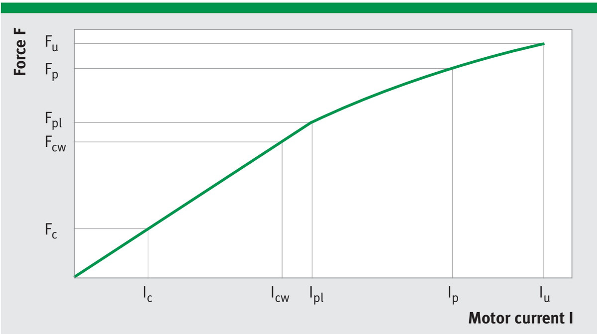
Force vs. current
Note:
The winding variant WM (standard) described above is suitable for moderately dynamic performance requirements. The winding variants WL and WH suitable for lower and higher dynamic performance requirements are available upon request. The integrated temperature sensors do not display the exact winding temperature. Depending on current load, the winding temperature may be up to approx. 30 K higher.
56
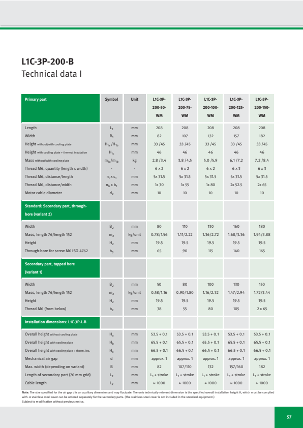
L1C-3P-200-B
Technical data I
| Primary part | Symbol | Unit | L1C-3P- 200-50- WM | L1C-3P- 200-75- WM | L1C-3P- 200-100- WM | L1C-3P- 200-125- WM | L1C-3P- 200-150- WM |
|---|---|---|---|---|---|---|---|
| Length | L₁ | mm | 208 | 208 | 208 | 208 | 208 |
| Width | B₁ | mm | 82 | 107 | 132 | 157 | 182 |
| Height without/with cooling plate | H₁a /H₁b | mm | 33 /45 | 33 /45 | 33 /45 | 33 /45 | 33 /45 |
| Height with cooling plate + thermal insulation | H₁c | mm | 46 | 46 | 46 | 46 | 46 |
| Mass without/with cooling plate | m₁a/m₁b | kg | 2.8 /3.4 | 3.8 /4.5 | 5.0 /5.9 | 6.1 /7.2 | 7.2 /8.4 |
| Thread M6, quantity (length x width) | - | - | 6 x 2 | 6 x 2 | 6 x 2 | 6 x 3 | 6 x 3 |
| Thread M6, distance/length | nₗ x c₁ | mm | 5x 31.5 | 5x 31.5 | 5x 31.5 | 5x 31.5 | 5x 31.5 |
| Thread M6, distance/width | nb x b₁ | mm | 1x 30 | 1x 55 | 1x 80 | 2x 52.5 | 2x 65 |
| Motor cable diameter | dK | mm | 10 | 10 | 10 | 10 | 10 |
| Standard: Secondary part, through- bore (variant 2) | |||||||
| Width | B₂ | mm | 80 | 110 | 130 | 160 | 180 |
| Mass, length 76/length 152 | m₂ | kg/unit | 0.78/1.56 | 1.11/2.22 | 1.36/2.72 | 1.68/3.36 | 1.94/3.88 |
| Height | H₂ | mm | 19.5 | 19.5 | 19.5 | 19.5 | 19.5 |
| Through-bore for screw M6 ISO 4762 | b₃ | mm | 65 | 90 | 115 | 140 | 165 |
| Secondary part, tapped bore (variant 1) | |||||||
| Width | B₂ | mm | 50 | 80 | 100 | 130 | 150 |
| Mass, length 76/length 152 | m₂ | kg/unit | 0.58/1.16 | 0.90/1.80 | 1.16/2.32 | 1.47/2.94 | 1.72/3.44 |
| Height | H₂ | mm | 19.5 | 19.5 | 19.5 | 19.5 | 19.5 |
| Thread M6 (from below) | b₂ | mm | 38 | 55 | 80 | 105 | 2 x 65 |
| Installation dimensions: L1C-3P-L-B | |||||||
| Overall height without cooling plate | Hₐ | mm | 53.5 + 0.1 | 53.5 + 0.1 | 53.5 + 0.1 | 53.5 + 0.1 | 53.5 + 0.1 |
| Overall height with cooling plate | Hb | mm | 65.5 + 0.1 | 65.5 + 0.1 | 65.5 + 0.1 | 65.5 + 0.1 | 65.5 + 0.1 |
| Overall height with cooling plate + therm. ins. | Hc | mm | 66.5 + 0.1 | 66.5 + 0.1 | 66.5 + 0.1 | 66.5 + 0.1 | 66.5 + 0.1 |
| Mechanical air gap | d | mm | approx. 1 | approx. 1 | approx. 1 | approx. 1 | approx. 1 |
| Max. width (depending on variant) | B | mm | 82 | 107/110 | 132 | 157/160 | 182 |
| Length of secondary part (76 mm grid) | L₂ | mm | L₁ + stroke | L₁ + stroke | L₁ + stroke | L₁ + stroke | L₁ + stroke |
| Cable length | LK | mm | ≈ 1000 | ≈ 1000 | ≈ 1000 | ≈ 1000 | ≈ 1000 |
Note: The size specified for the air gap d is an auxiliary dimension and may fluctuate. The only technically relevant dimension is the specified overall installation height H, which must be complied with. A stainless steel cover can be ordered separately for the secondary parts. (The stainless steel cover is not included in the standard equipment.)
Subject to modification without previous notice.
57
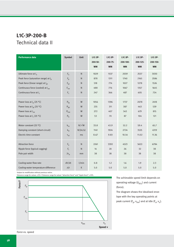
L1C-3P-200-B
Technical data II
| Performance data | Symbol | Unit | L1C-3P-200-50-WM | L1C-3P-200-75-WM | L1C-3P-200-100-WM | L1C-3P-200-125-WM | L1C-3P-200-150-WM |
|---|---|---|---|---|---|---|---|
| Ultimate force at Iu | Fu | N | 1029 | 1537 | 2039 | 2537 | 3030 |
| Peak force (saturation range) at Ip | Fp | N | 878 | 1311 | 1740 | 2165 | 2586 |
| Peak force (linear range) at Ipl | Fpl | N | 518 | 774 | 1027 | 1278 | 1526 |
| Continuous force (cooled) at Icw | Fcw | N | 488 | 776 | 1067 | 1357 | 1645 |
| Continuous force at Ic | Fc | N | 247 | 366 | 487 | 605 | 724 |
| Power loss at Ip (25 °C) | Plp | W | 1056 | 1396 | 1737 | 2078 | 2418 |
| Power loss at Ipl (25 °C) | Plpl | W | 235 | 311 | 387 | 463 | 539 |
| Power loss at Icw | Plcw | W | 272 | 407 | 543 | 679 | 815 |
| Power loss at Ic (25 °C) | Plc | W | 53 | 70 | 87 | 104 | 121 |
| Motor constant (25 °C) | km | N/√W | 33.8 | 43.9 | 52.2 | 59.4 | 65.7 |
| Damping constant (short-circuit) | kd | N/(m/s) | 1141 | 1924 | 2724 | 3525 | 4319 |
| Electric time constant | τel | ms | 8.67 | 9.83 | 10.54 | 11.02 | 11.36 |
| Attraction force | Fa | N | 2261 | 3392 | 4523 | 5653 | 6784 |
| Ripple force (typical cogging) | Fr | N | 14 | 20 | 26 | 32 | 38 |
| Pole pair width | 2τp | mm | 38 | 38 | 38 | 38 | 38 |
| Cooling-water flow-rate | dV/dt | l/min | 0.8 | 1.2 | 1.6 | 1.9 | 2.3 |
| Cooling-water temperature-difference | Δϑ | K | 5.0 | 5.0 | 5.0 | 5.0 | 5.0 |
Subject to modification without previous notice.
Tolerance range for values: ±5% • Tolerance range for values “attraction force” and “ripple force”: ±10%
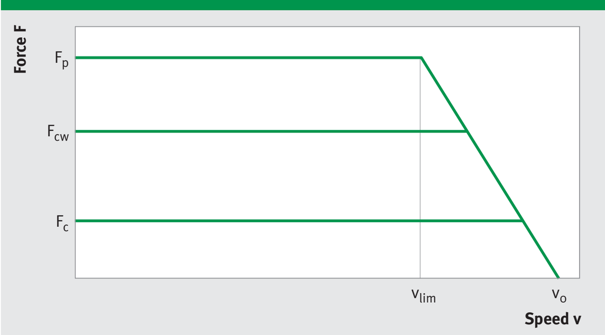
Force vs. speed
The achievable speed limit depends on operating voltage (U_DCL) and current (force).
The diagram shows the idealised envelope with the key operating points at peak current (Fₚ, vₗᵢₘ) and at idle (Fₒ, vₒ).
58
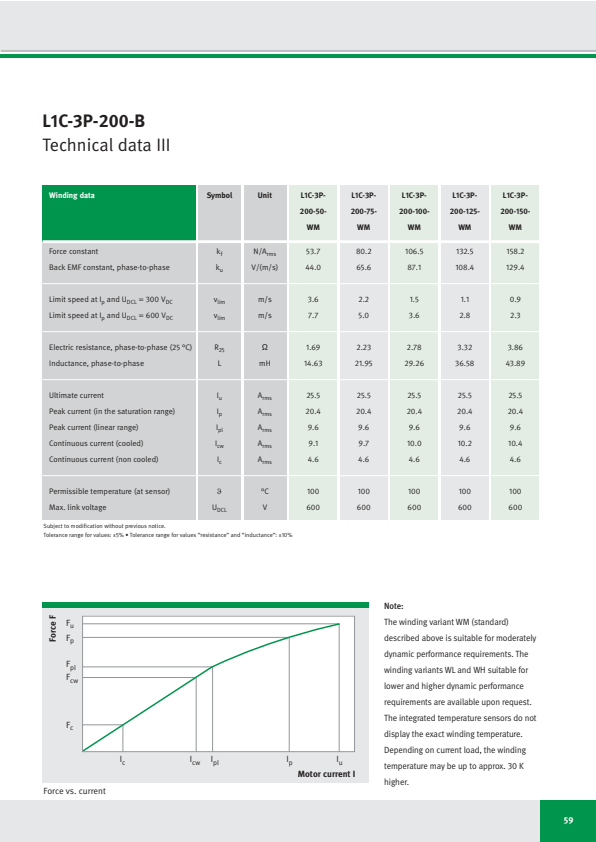
L1C-3P-200-B
Technical data III
| Winding data | Symbol | Unit | L1C-3P-200-50-WM | L1C-3P-200-75-WM | L1C-3P-200-100-WM | L1C-3P-200-125-WM | L1C-3P-200-150-WM |
|---|---|---|---|---|---|---|---|
| Force constant | kf | N/Arms | 53.7 | 80.2 | 106.5 | 132.5 | 158.2 |
| Back EMF constant, phase-to-phase | ku | V/(m/s) | 44.0 | 65.6 | 87.1 | 108.4 | 129.4 |
| Limit speed at Ip and UDCL = 300 VDC | vlim | m/s | 3.6 | 2.2 | 1.5 | 1.1 | 0.9 |
| Limit speed at Ip and UDCL = 600 VDC | vlim | m/s | 7.7 | 5.0 | 3.6 | 2.8 | 2.3 |
| Electric resistance, phase-to-phase (25 °C) | R25 | Ω | 1.69 | 2.23 | 2.78 | 3.32 | 3.86 |
| Inductance, phase-to-phase | L | mH | 14.63 | 21.95 | 29.26 | 36.58 | 43.89 |
| Ultimate current | Iu | Arms | 25.5 | 25.5 | 25.5 | 25.5 | 25.5 |
| Peak current (in the saturation range) | Ip | Arms | 20.4 | 20.4 | 20.4 | 20.4 | 20.4 |
| Peak current (linear range) | Ipl | Arms | 9.6 | 9.6 | 9.6 | 9.6 | 9.6 |
| Continuous current (cooled) | Icw | Arms | 9.1 | 9.7 | 10.0 | 10.2 | 10.4 |
| Continuous current (non cooled) | Ic | Arms | 4.6 | 4.6 | 4.6 | 4.6 | 4.6 |
| Permissible temperature (at sensor) | ϑ | °C | 100 | 100 | 100 | 100 | 100 |
| Max. link voltage | UDCL | V | 600 | 600 | 600 | 600 | 600 |
Subject to modification without previous notice.
Tolerance range for values: ±5% • Tolerance range for values “resistance” and “inductance”: ±10%
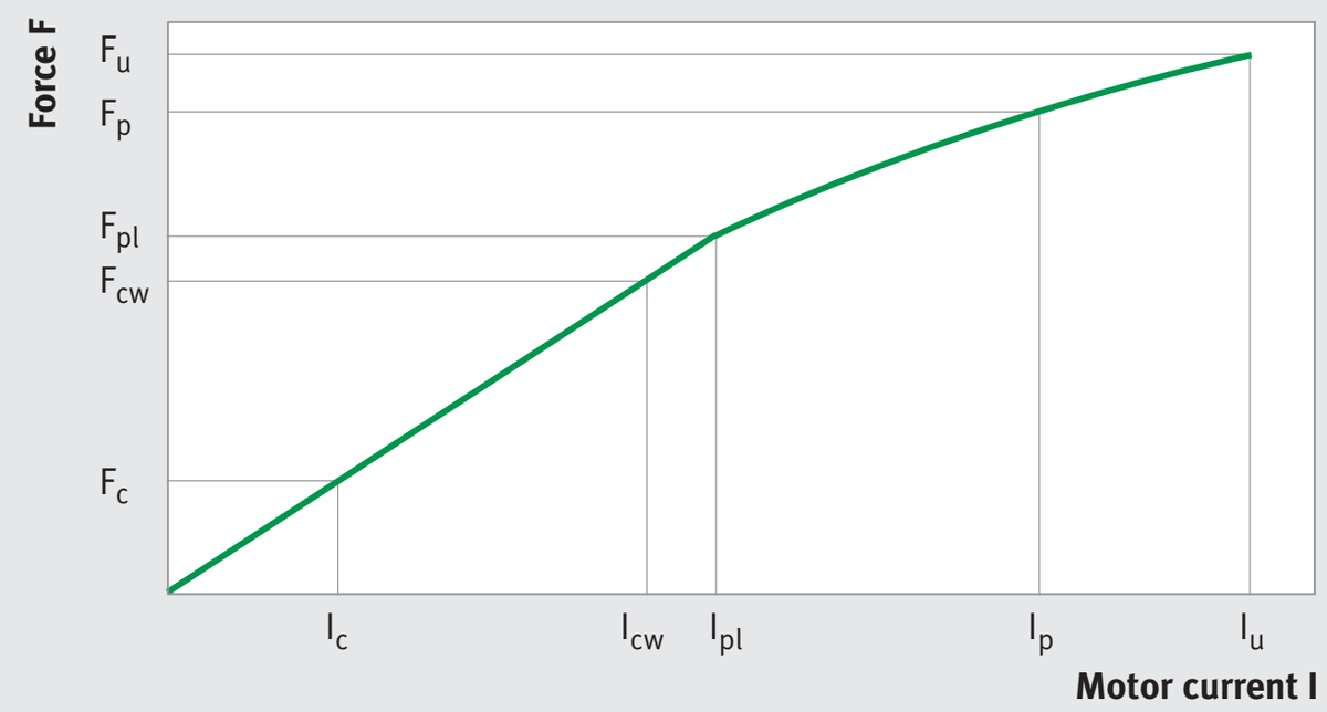
同じ画像がページ 65 にも表示されています
Force vs. current
Note:
The winding variant WM (standard) described above is suitable for moderately dynamic performance requirements. The winding variants WL and WH suitable for lower and higher dynamic performance requirements are available upon request. The integrated temperature sensors do not display the exact winding temperature. Depending on current load, the winding temperature may be up to approx. 30 K higher.
59
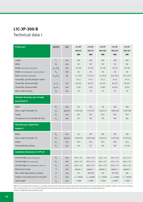
L1C-3P-300-B
Technical data I
| Primary part | Symbol | Unit | L1C-3P- 300-50- WM | L1C-3P- 300-75- WM | L1C-3P- 300-100- WM | L1C-3P- 300-125- WM | L1C-3P- 300-150- WM |
|---|---|---|---|---|---|---|---|
| Length | L₁ | mm | 303 | 303 | 303 | 303 | 303 |
| Width | B₁ | mm | 82 | 107 | 132 | 157 | 182 |
| Height without/with cooling plate | H1a /H1b | mm | 33 /45 | 33 /45 | 33 /45 | 33 /45 | 33 /45 |
| Height with cooling plate + thermal insulation | H1c | mm | 46 | 46 | 46 | 46 | 46 |
| Mass without/with cooling plate | m1a/m1b | kg | 4.1 /4.9 | 5.7 /6.7 | 7.3 /8.6 | 8.9 /10.4 | 10.5 /12.2 |
| Thread M6, quantity (length x width) | - | - | 9 x 2 | 9 x 2 | 9 x 2 | 9 x 3 | 9 x 3 |
| Thread M6, distance/length | nₗ x c₁ | mm | 8x 31.5 | 8x 31.5 | 8x 31.5 | 8x 31.5 | 8x 31.5 |
| Thread M6, distance/width | nb x b₁ | mm | 1x 30 | 1x 55 | 1x 80 | 2x 52.5 | 2x 65 |
| Motor cable diameter | dK | mm | 10 | 10 | 10 | 10 | 10 |
| Standard: Secondary part, through- bore (variant 2) | |||||||
| Width | B₂ | mm | 80 | 110 | 130 | 160 | 180 |
| Mass, length 76/length 152 | m₂ | kg/unit | 0.78/1.56 | 1.11/2.22 | 1.36/2.72 | 1.68/3.36 | 1.94/3.88 |
| Height | H₂ | mm | 19.5 | 19.5 | 19.5 | 19.5 | 19.5 |
| Through-bore for screw M6 ISO 4762 | b₃ | mm | 65 | 90 | 115 | 140 | 165 |
| Secondary part, tapped bore (variant 1) | |||||||
| Width | B₂ | mm | 50 | 80 | 100 | 130 | 150 |
| Mass, length 76/length 152 | m₂ | kg/unit | 0.58/1.16 | 0.90/1.80 | 1.16/2.32 | 1.47/2.94 | 1.72/3.44 |
| Height | H₂ | mm | 19.5 | 19.5 | 19.5 | 19.5 | 19.5 |
| Thread M6 (from below) | b₂ | mm | 38 | 55 | 80 | 105 | 2 x 65 |
| Installation dimensions: L1C-3P-L-B | |||||||
| Overall height without cooling plate | Ha | mm | 53.5 + 0.1 | 53.5 + 0.1 | 53.5 + 0.1 | 53.5 + 0.1 | 53.5 + 0.1 |
| Overall height with cooling plate | Hb | mm | 65.5 + 0.1 | 65.5 + 0.1 | 65.5 + 0.1 | 65.5 + 0.1 | 65.5 + 0.1 |
| Overall height with cooling plate + therm. ins. | Hc | mm | 66.5 + 0.1 | 66.5 + 0.1 | 66.5 + 0.1 | 66.5 + 0.1 | 66.5 + 0.1 |
| Mechanical air gap | d | mm | approx. 1 | approx. 1 | approx. 1 | approx. 1 | approx. 1 |
| Max. width (depending on variant) | B | mm | 82 | 107/110 | 132 | 157/160 | 182 |
| Length of secondary part (76 mm grid) | L₂ | mm | L₁ + stroke | L₁ + stroke | L₁ + stroke | L₁ + stroke | L₁ + stroke |
| Cable length | LK | mm | ≈ 1000 | ≈ 1000 | ≈ 1000 | ≈ 1000 | ≈ 1000 |
Note: The size specified for the air gap d is an auxiliary dimension and may fluctuate. The only technically relevant dimension is the specified overall installation height H, which must be complied with. A stainless steel cover can be ordered separately for the secondary parts. (The stainless steel cover is not included in the standard equipment.)
Subject to modification without previous notice.
60
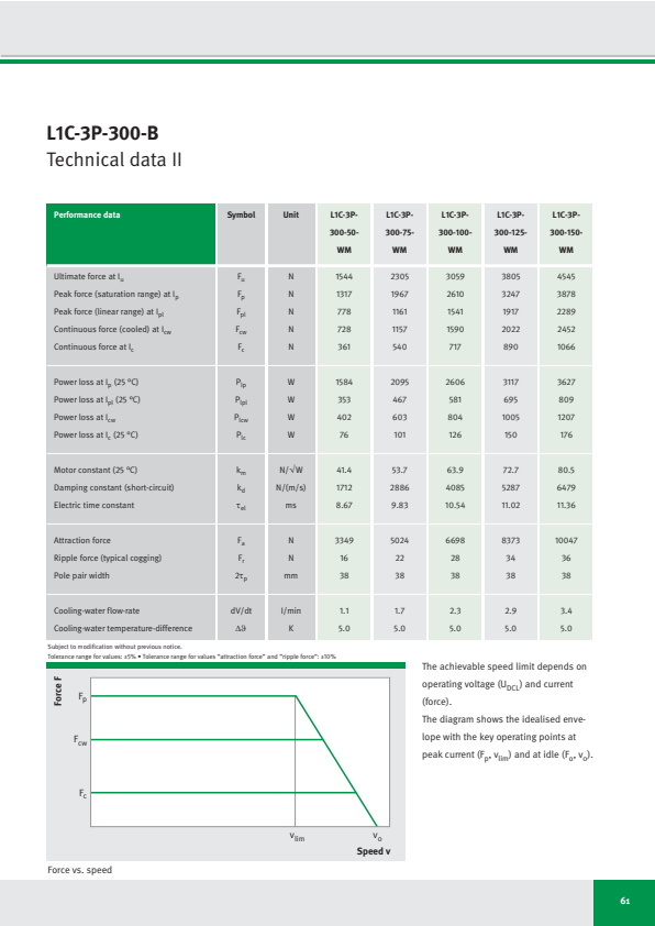
L1C-3P-300-B
Technical data II
| Performance data | Symbol | Unit | L1C-3P- 300-50- WM | L1C-3P- 300-75- WM | L1C-3P- 300-100- WM | L1C-3P- 300-125- WM | L1C-3P- 300-150- WM |
|---|---|---|---|---|---|---|---|
| Ultimate force at Iu | Fu | N | 1544 | 2305 | 3059 | 3805 | 4545 |
| Peak force (saturation range) at Ip | Fp | N | 1317 | 1967 | 2610 | 3247 | 3878 |
| Peak force (linear range) at Ipl | Fpl | N | 778 | 1161 | 1541 | 1917 | 2289 |
| Continuous force (cooled) at Icw | Fcw | N | 728 | 1157 | 1590 | 2022 | 2452 |
| Continuous force at Ic | Fc | N | 361 | 540 | 717 | 890 | 1066 |
| Power loss at Ip (25 °C) | Plp | W | 1584 | 2095 | 2606 | 3117 | 3627 |
| Power loss at Ipl (25 °C) | Plpl | W | 353 | 467 | 581 | 695 | 809 |
| Power loss at Icw | Picw | W | 402 | 603 | 804 | 1005 | 1207 |
| Power loss at Ic (25 °C) | Plc | W | 76 | 101 | 126 | 150 | 176 |
| Motor constant (25 °C) | km | N/√W | 41.4 | 53.7 | 63.9 | 72.7 | 80.5 |
| Damping constant (short-circuit) | kd | N/(m/s) | 1712 | 2886 | 4085 | 5287 | 6479 |
| Electric time constant | τel | ms | 8.67 | 9.83 | 10.54 | 11.02 | 11.36 |
| Attraction force | Fa | N | 3349 | 5024 | 6698 | 8373 | 10047 |
| Ripple force (typical cogging) | Fr | N | 16 | 22 | 28 | 34 | 36 |
| Pole pair width | 2τp | mm | 38 | 38 | 38 | 38 | 38 |
| Cooling-water flow-rate | dV/dt | l/min | 1.1 | 1.7 | 2.3 | 2.9 | 3.4 |
| Cooling-water temperature-difference | Δϑ | K | 5.0 | 5.0 | 5.0 | 5.0 | 5.0 |
Subject to modification without previous notice.
Tolerance range for values: ±5% • Tolerance range for values “attraction force” and “ripple force”: ±10%
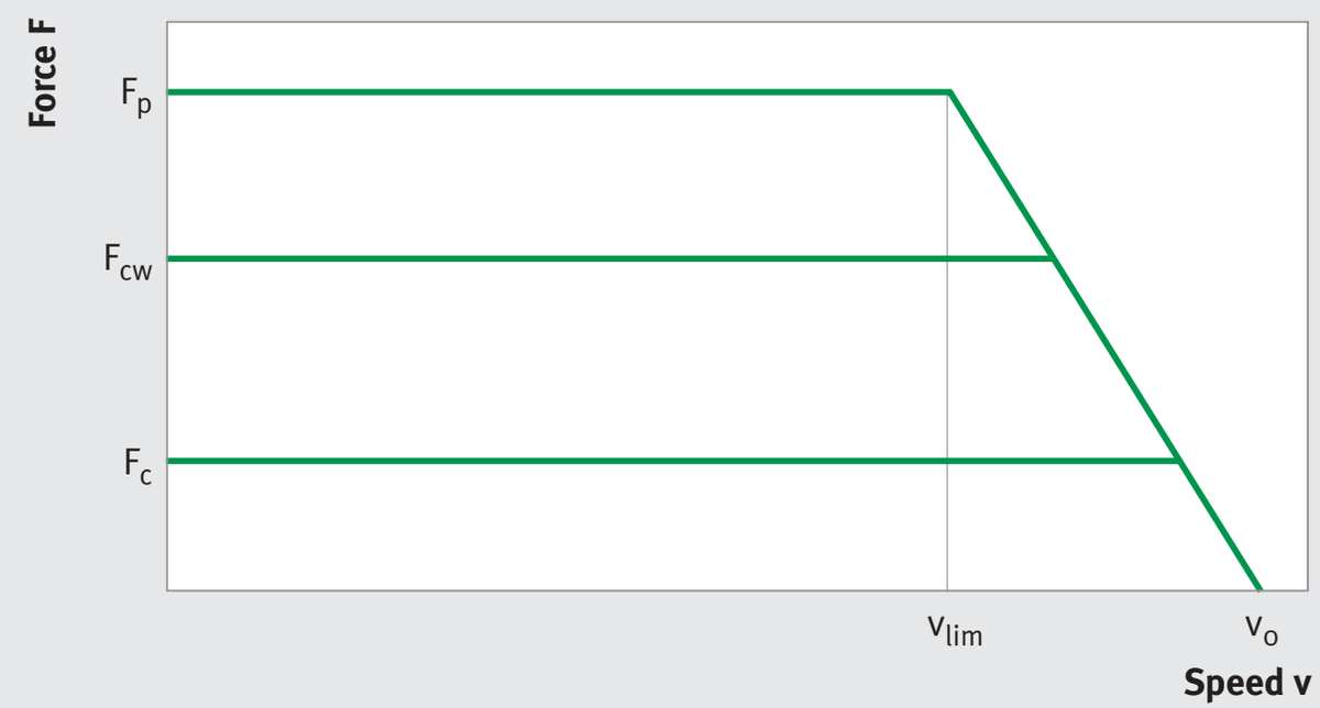
Force vs. speed
The achievable speed limit depends on operating voltage (U_DCL) and current (force).
The diagram shows the idealised envelope with the key operating points at peak current (Fₚ, vₗᵢₘ) and at idle (Fₒ, vₒ).
61
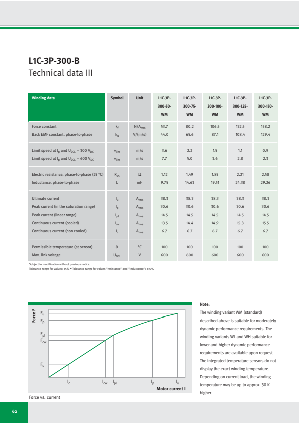
L1C-3P-300-B
Technical data III
| Winding data | Symbol | Unit | L1C-3P-300-50-WM | L1C-3P-300-75-WM | L1C-3P-300-100-WM | L1C-3P-300-125-WM | L1C-3P-300-150-WM |
|---|---|---|---|---|---|---|---|
| Force constant | k_f | N/A_rms | 53.7 | 80.2 | 106.5 | 132.5 | 158.2 |
| Back EMF constant, phase-to-phase | k_u | V/(m/s) | 44.0 | 65.6 | 87.1 | 108.4 | 129.4 |
| Limit speed at I_p and U_DCL = 300 V_DC | v_lim | m/s | 3.6 | 2.2 | 1.5 | 1.1 | 0.9 |
| Limit speed at I_p and U_DCL = 600 V_DC | v_lim | m/s | 7.7 | 5.0 | 3.6 | 2.8 | 2.3 |
| Electric resistance, phase-to-phase (25 °C) | R_25 | Ω | 1.12 | 1.49 | 1.85 | 2.21 | 2.58 |
| Inductance, phase-to-phase | L | mH | 9.75 | 14.63 | 19.51 | 24.38 | 29.26 |
| Ultimate current | I_u | A_rms | 38.3 | 38.3 | 38.3 | 38.3 | 38.3 |
| Peak current (in the saturation range) | I_p | A_rms | 30.6 | 30.6 | 30.6 | 30.6 | 30.6 |
| Peak current (linear range) | I_pl | A_rms | 14.5 | 14.5 | 14.5 | 14.5 | 14.5 |
| Continuous current (cooled) | I_cw | A_rms | 13.5 | 14.4 | 14.9 | 15.3 | 15.5 |
| Continuous current (non cooled) | I_c | A_rms | 6.7 | 6.7 | 6.7 | 6.7 | 6.7 |
| Permissible temperature (at sensor) | ϑ | °C | 100 | 100 | 100 | 100 | 100 |
| Max. link voltage | U_DCL | V | 600 | 600 | 600 | 600 | 600 |
Subject to modification without previous notice.
Tolerance range for values: ±5% • Tolerance range for values "resistance" and "inductance": ±10%
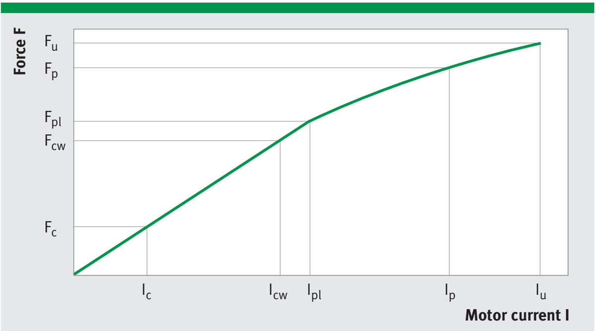
Force vs. current
Note:
The winding variant WM (standard) described above is suitable for moderately dynamic performance requirements. The winding variants WL and WH suitable for lower and higher dynamic performance requirements are available upon request. The integrated temperature sensors do not display the exact winding temperature. Depending on current load, the winding temperature may be up to approx. 30 K higher.
62
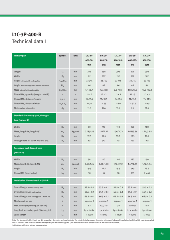
L1C-3P-400-B
Technical data I
| Primary part | Symbol | Unit | L1C-3P- 400-50- WM | L1C-3P- 400-75- WM | L1C-3P- 400-100- WM | L1C-3P- 400-125- WM | L1C-3P- 400-150- WM |
|---|---|---|---|---|---|---|---|
| Length | L₁ | mm | 398 | 398 | 398 | 398 | 398 |
| Width | B₁ | mm | 82 | 107 | 132 | 157 | 182 |
| Height without/with cooling plate | H₁a /H1b | mm | 33 /45 | 33 /45 | 33 /45 | 33 /45 | 33 /45 |
| Height with cooling plate + thermal insulation | H1c | mm | 46 | 46 | 46 | 46 | 46 |
| Mass without/with cooling plate | m1a/m1b | kg | 5.4 /6.4 | 7.5 /8.8 | 9.6 /11.3 | 11.8 /13.8 | 13.9 /16.2 |
| Thread M6, quantity (length x width) | - | - | 12 x 2 | 12 x 2 | 12 x 2 | 12 x 3 | 12 x 3 |
| Thread M6, distance/length | nl x c₁ | mm | 11x 31.5 | 11x 31.5 | 11x 31.5 | 11x 31.5 | 11x 31.5 |
| Thread M6, distance/width | nb x b₁ | mm | 1x 30 | 1x 55 | 1x 80 | 2x 52.5 | 2x 65 |
| Motor cable diameter | dK | mm | 11.6 | 11.6 | 11.6 | 11.6 | 11.6 |
| Standard: Secondary part, through- bore (variant 2) | |||||||
| Width | B₂ | mm | 80 | 110 | 130 | 160 | 180 |
| Mass, length 76/length 152 | m₂ | kg/unit | 0.78/1.56 | 1.11/2.22 | 1.36/2.72 | 1.68/3.36 | 1.94/3.88 |
| Height | H₂ | mm | 19.5 | 19.5 | 19.5 | 19.5 | 19.5 |
| Through-bore for screw M6 ISO 4762 | b₃ | mm | 65 | 90 | 115 | 140 | 165 |
| Secondary part, tapped bore (variant 1) | |||||||
| Width | B₂ | mm | 50 | 80 | 100 | 130 | 150 |
| Mass, length 76/length 152 | m₂ | kg/unit | 0.58/1.16 | 0.90/1.80 | 1.16/2.32 | 1.47/2.94 | 1.72/3.44 |
| Height | H₂ | mm | 19.5 | 19.5 | 19.5 | 19.5 | 19.5 |
| Thread M6 (from below) | b₂ | mm | 38 | 55 | 80 | 105 | 2 x 65 |
| Installation dimensions: L1C-3P-L-B | |||||||
| Overall height without cooling plate | Ha | mm | 53.5 + 0.1 | 53.5 + 0.1 | 53.5 + 0.1 | 53.5 + 0.1 | 53.5 + 0.1 |
| Overall height with cooling plate | Hb | mm | 65.5 + 0.1 | 65.5 + 0.1 | 65.5 + 0.1 | 65.5 + 0.1 | 65.5 + 0.1 |
| Overall height with cooling plate + therm. ins. | Hc | mm | 66.5 + 0.1 | 66.5 + 0.1 | 66.5 + 0.1 | 66.5 + 0.1 | 66.5 + 0.1 |
| Mechanical air gap | d | mm | approx. 1 | approx. 1 | approx. 1 | approx. 1 | approx. 1 |
| Max. width (depending on variant) | B | mm | 82 | 107/110 | 132 | 157/160 | 182 |
| Length of secondary part (76 mm grid) | L₂ | mm | L₁ + stroke | L₁ + stroke | L₁ + stroke | L₁ + stroke | L₁ + stroke |
| Cable length | LK | mm | ≈ 1000 | ≈ 1000 | ≈ 1000 | ≈ 1000 | ≈ 1000 |
Note: The size specified for the air gap d is an auxiliary dimension and may fluctuate. The only technically relevant dimension is the specified overall installation height H, which must be complied with. A stainless steel cover can be ordered separately for the secondary parts. (The stainless steel cover is not included in the standard equipment.)
Subject to modification without previous notice.
63
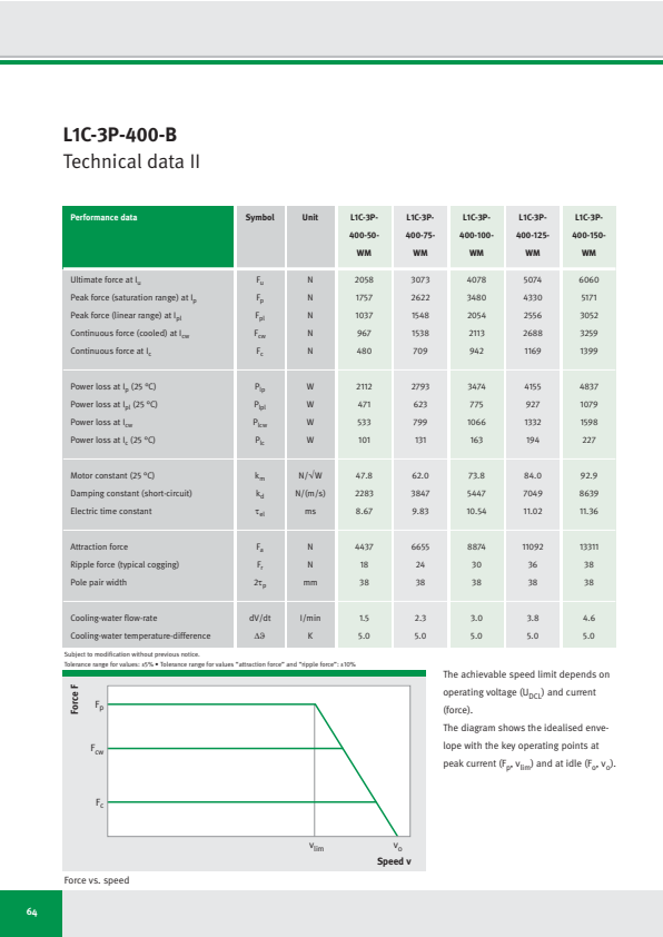
L1C-3P-400-B
Technical data II
| Performance data | Symbol | Unit | L1C-3P-400-50-WM | L1C-3P-400-75-WM | L1C-3P-400-100-WM | L1C-3P-400-125-WM | L1C-3P-400-150-WM |
|---|---|---|---|---|---|---|---|
| Ultimate force at Iu | Fu | N | 2058 | 3073 | 4078 | 5074 | 6060 |
| Peak force (saturation range) at Ip | Fp | N | 1757 | 2622 | 3480 | 4330 | 5171 |
| Peak force (linear range) at Ipl | Fpl | N | 1037 | 1548 | 2054 | 2556 | 3052 |
| Continuous force (cooled) at Icw | Fcw | N | 967 | 1538 | 2113 | 2688 | 3259 |
| Continuous force at Ic | Fc | N | 480 | 709 | 942 | 1169 | 1399 |
| Power loss at Ip (25 °C) | Plp | W | 2112 | 2793 | 3474 | 4155 | 4837 |
| Power loss at Ipl (25 °C) | Plpl | W | 471 | 623 | 775 | 927 | 1079 |
| Power loss at Icw | Plcw | W | 533 | 799 | 1066 | 1332 | 1598 |
| Power loss at Ic (25 °C) | Plc | W | 101 | 131 | 163 | 194 | 227 |
| Motor constant (25 °C) | km | N/√W | 47.8 | 62.0 | 73.8 | 84.0 | 92.9 |
| Damping constant (short-circuit) | kd | N/(m/s) | 2283 | 3847 | 5447 | 7049 | 8639 |
| Electric time constant | τel | ms | 8.67 | 9.83 | 10.54 | 11.02 | 11.36 |
| Attraction force | Fa | N | 4437 | 6655 | 8874 | 11092 | 13311 |
| Ripple force (typical cogging) | Fr | N | 18 | 24 | 30 | 36 | 38 |
| Pole pair width | 2τp | mm | 38 | 38 | 38 | 38 | 38 |
| Cooling-water flow-rate | dV/dt | l/min | 1.5 | 2.3 | 3.0 | 3.8 | 4.6 |
| Cooling-water temperature-difference | Δϑ | K | 5.0 | 5.0 | 5.0 | 5.0 | 5.0 |
Subject to modification without previous notice.
Tolerance range for values: ±5% • Tolerance range for values “attraction force” and “ripple force”: ±10%
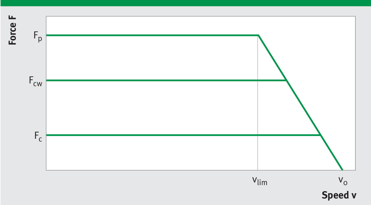
Force vs. speed
The achievable speed limit depends on operating voltage (U_DCL) and current (force).
The diagram shows the idealised envelope with the key operating points at peak current (Fₚ, vₗᵢₘ) and at idle (Fₒ, vₒ).
64
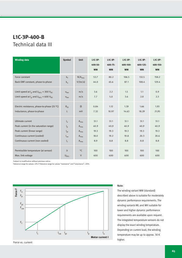
L1C-3P-400-B
Technical data III
| Winding data | Symbol | Unit | L1C-3P-400-50-WM | L1C-3P-400-75-WM | L1C-3P-400-100-WM | L1C-3P-400-125-WM | L1C-3P-400-150-WM |
|---|---|---|---|---|---|---|---|
| Force constant | kf | N/Arms | 53.7 | 80.2 | 106.5 | 132.5 | 158.2 |
| Back EMF constant, phase-to-phase | ku | V/(m/s) | 44.0 | 65.6 | 87.1 | 108.4 | 129.4 |
| Limit speed at Ip and UDCL = 300 VDC | vlim | m/s | 3.6 | 2.2 | 1.5 | 1.1 | 0.9 |
| Limit speed at Ip and UDCL = 600 VDC | vlim | m/s | 7.7 | 5.0 | 3.6 | 2.8 | 2.3 |
| Electric resistance, phase-to-phase (25 °C) | R25 | Ω | 0.84 | 1.12 | 1.39 | 1.66 | 1.93 |
| Inductance, phase-to-phase | L | mH | 7.32 | 10.97 | 14.63 | 18.29 | 21.95 |
| Ultimate current | Iu | Arms | 51.1 | 51.1 | 51.1 | 51.1 | 51.1 |
| Peak current (in the saturation range) | Ip | Arms | 40.9 | 40.9 | 40.9 | 40.9 | 40.9 |
| Peak current (linear range) | Ipl | Arms | 19.3 | 19.3 | 19.3 | 19.3 | 19.3 |
| Continuous current (cooled) | Icw | Arms | 18.0 | 19.2 | 19.8 | 20.3 | 20.6 |
| Continuous current (non cooled) | Ic | Arms | 8.9 | 8.8 | 8.8 | 8.8 | 8.8 |
| Permissible temperature (at sensor) | ϑ | °C | 100 | 100 | 100 | 100 | 100 |
| Max. link voltage | UDCL | V | 600 | 600 | 600 | 600 | 600 |
Subject to modification without previous notice.
Tolerance range for values: ±5% • Tolerance range for values “resistance” and “inductance”: ±10%
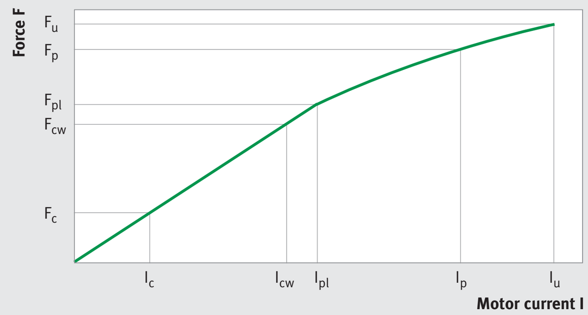
同じ画像がページ 59 にも表示されています
Force vs. current
Note:
The winding variant WM (standard) described above is suitable for moderately dynamic performance requirements. The winding variants WL and WH suitable for lower and higher dynamic performance requirements are available upon request. The integrated temperature sensors do not display the exact winding temperature. Depending on current load, the winding temperature may be up to approx. 30 K higher.
65

Check List for Your Enquiry
Send by fax to: +49 3681 7574-30
This check list can also be downloaded from the download centre at www.idam.de.
| Company | Contact person | Industry / appellation of project |
|---|---|---|
| Telephone | Fax | |
Spatial position of drive axis
Installation conditions for drive
(sketch or drawing, if appropriate)
Max. installation dimensions [mm]:
(length/width/height)
Shortest acceleration
and/or deceleration time [ms]:
66
この表はこのページから抽出されましたが、正確な位置を特定できなかったため、ここ(末尾)に表示しています。
| Brief description | ||
|---|---|---|
| Motor ☐ | System ☐ | Axis within a multi-axis system ☐ |
この表はこのページから抽出されましたが、正確な位置を特定できなかったため、ここ(末尾)に表示しています。
| Spatial position of drive axis | |
|---|---|
| Type of weight compensation: | |
| Installation conditions for drive (sketch or drawing, if appropriate) | |
| Max. installation dimensions [mm]: (length/width/height) | |
| Mechanical interface: | |
| Ambient conditions | |
| Temperature [K]: | |
| Contamination: | |
| Protection class (IP): | |
| Motion variables | |
| Stroke s [mm]: | |
| Payload [kg]: | |
| External forces [N]: | |
| Maximum speed [m/s]: | |
| Constant velocity fluctuations [%] at: | |
| Shortest acceleration and/or deceleration time [ms]: | |
| Overshoot in position [µm]: | |
| Settling time [ms]: | |
| Typical cycle per time (diagram): | |
| Service life/operating hours [h]: | |
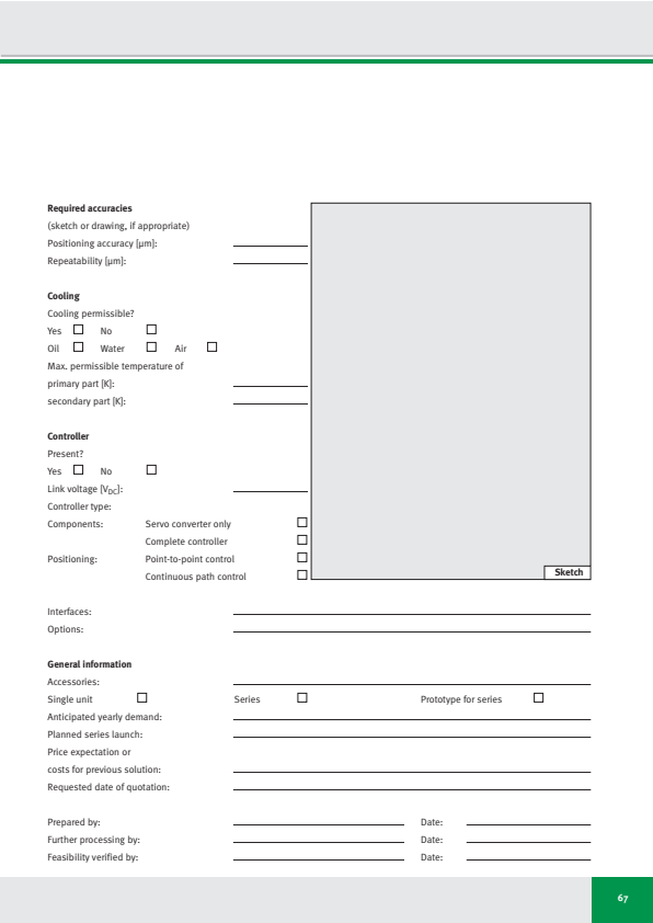
Required accuracies
(sketch or drawing, if appropriate)
Positioning accuracy [μm]:
Repeatability [μm]:
Cooling
Cooling permissible?
Yes
No
Oil
Water
Air
Max. permissible temperature of
primary part [K]:
secondary part [K]:
Controller
Present?
Yes
No
Link voltage [V_DC] :
Controller type:
Components:
Servo converter only
Complete controller
Positioning:
Point-to-point control
Continuous path control
Interfaces:
Options:
General information
Accessories:
Single unit
Series
Prototype for series
Anticipated yearly demand:
Planned series launch:
Price expectation or
costs for previous solution:
Requested date of quotation:
Prepared by:
Further processing by:
Feasibility verified by:
Date:
Date:
Date:
67
Required accuracies Sketch Sketch
(sketch or drawing, if appropriate) Sketch Sketch
Positioning accuracy [µm]: Sketch Sketch
Repeatability [µm]: Sketch Sketch
Cooling Sketch Sketch
Cooling permissible? Sketch Sketch
Yes ☐ No ☐ Sketch Sketch
Oil ☐ Water ☐ Air ☐ Sketch Sketch
Max. permissible temperature of Sketch Sketch
primary part [K]: Sketch Sketch
secondary part [K]: Sketch Sketch
Controller Sketch Sketch
Present? Sketch Sketch
Yes ☐ No ☐ Sketch Sketch
Link voltage [VDC]: Sketch Sketch
Controller type: Sketch Sketch
Components: Servo converter only Servo converter only Servo converter only Servo converter only Servo converter only Servo converter only ☐
Complete controller Complete controller Complete controller Complete controller Complete controller Complete controller ☐
Positioning: Point-to-point control Point-to-point control Point-to-point control Point-to-point control Point-to-point control Point-to-point control ☐
Continuous path control Continuous path control Continuous path control Continuous path control Continuous path control Continuous path control ☐
Interfaces:
Options:
General information
Accessories:
Single unit ☐ Series ☐ Prototype for series Prototype for series ☐
Anticipated yearly demand:
Planned series launch:
Price expectation or
costs for previous solution:
Requested date of quotation:
Prepared by: Date:
Further processing by: Date:
Feasibility verified by: Date:

Technical Information and Consulting Services
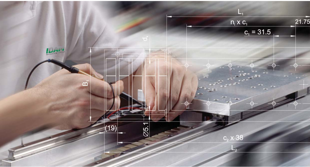
Class-leading technology and competent consulting services are two of the major benefits of working with IDAM.
IDAM application engineers are looking forward to support you choose the perfect drive for your application.
Please contact us:
Phone: +49 3681 7574-0
Industry: Automation/Medical Technology
E-mail: [email protected]
Industry: Productronics/Measuring Technology
E-mail: [email protected]
Industry: Production Machinery/Heavy Industries
E-mail: [email protected]
Industry: Automotive
E-mail: [email protected]
68

IDAM Worldwide
Austria
Phone: +43 2672 2023332
E-mail: [email protected]
Canada
Phone: +780 980 3016
E-mail: [email protected]
China
Phone: +86 21 39576612
E-mail: [email protected]
Finland
Phone: +358 207 366238
E-mail: [email protected]
Israel
Phone: +972 3 5441941
E-mail: [email protected]
Italy
Phone: +39 0321 929267
E-mail: [email protected]
Japan
Phone: +81 45 4765913
E-mail: [email protected]
Korea
Phone: +82 2 311 3096
E-mail: [email protected]
Netherlands
Phone: +31 342 403208
E-mail: [email protected]
Russia
Phone: +7 495 7377660
E-mail: [email protected]
Singapore
Phone: +65 6540 8616
E-mail: [email protected]
Spain/Portugal
Phone: +34 93 4803679
E-mail: [email protected]
Switzerland
Phone: +41 71 4666312
E-mail: [email protected]
Taiwan
E-mail: [email protected]
United Kingdom
E-mail: [email protected]
USA
Phone: +1 704 5167517
E-mail: [email protected]
Other countries:
E-mail: [email protected]
69
Phone: +43 2672 2023332 Phone: +81 45 4765913 Phone: +41 71 4666312
E-mail: [email protected] E-mail: [email protected] E-mail: [email protected]
Canada Canada Korea Korea Taiwan Taiwan
Phone: +780 980 3016 Phone: +82 2 311 3096 E-mail: [email protected]
E-mail: [email protected] E-mail: [email protected]
China China Netherlands Netherlands United Kingdom United Kingdom
Phone: +86 21 39576612 Phone: +31 342 403208 E-mail: [email protected]
E-mail: [email protected] E-mail: [email protected]
Finland Finland Russia Russia USA USA
Phone: +358 207 366238 Phone: +7 495 7377660 Phone: +1 704 5167517
E-mail: [email protected] E-mail: [email protected] E-mail: [email protected]
Israel Israel Singapore Singapore Other countries: Other countries:
Phone: +972 3 5441941 Phone: +65 6540 8616 E-mail: [email protected]
E-mail: [email protected] E-mail: [email protected]
Italy Italy Spain/Portugal Spain/Portugal
Phone: +39 0321 929267 Phone: +34 93 4803679
E-mail: [email protected] E-mail: [email protected]
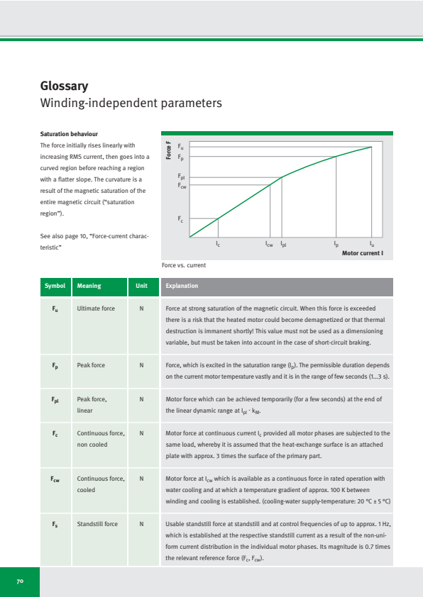
Glossary
Winding-independent parameters
Saturation behaviour
The force initially rises linearly with increasing RMS current, then goes into a curved region before reaching a region with a flatter slope. The curvature is a result of the magnetic saturation of the entire magnetic circuit (“saturation region”).
See also page 10, “Force-current characteristic”
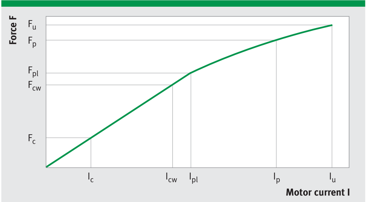
Force vs. current
| Symbol | Meaning | Unit | Explanation |
|---|---|---|---|
| Fu | Ultimate force | N | Force at strong saturation of the magnetic circuit. When this force is exceeded there is a risk that the heated motor could become demagnetized or that thermal destruction is immanent shortly! This value must not be used as a dimensioning variable, but must be taken into account in the case of short-circuit braking. |
| Fp | Peak force | N | Force, which is excited in the saturation range (Ip). The permissible duration depends on the current motor temperature vastly and it is in the range of few seconds (1...3 s). |
| Fpl | Peak force, linear | N | Motor force which can be achieved temporarily (for a few seconds) at the end of the linear dynamic range at Ipl · kM. |
| Fc | Continuous force, non cooled | N | Motor force at continuous current Ic provided all motor phases are subjected to the same load, whereby it is assumed that the heat-exchange surface is an attached plate with approx. 3 times the surface of the primary part. |
| Fcw | Continuous force, cooled | N | Motor force at Icw which is available as a continuous force in rated operation with water cooling and at which a temperature gradient of approx. 100 K between winding and cooling is established. (cooling-water supply-temperature: 20 °C ± 5 °C) |
| Fs | Standstill force | N | Usable standstill force at standstill and at control frequencies of up to approx. 1 Hz, which is established at the respective standstill current as a result of the non-uniform current distribution in the individual motor phases. Its magnitude is 0.7 times the relevant reference force (Fc, Fcw). |
70
| Symbol | Meaning | Unit | Explanation |
|---|---|---|---|
| P l | Power loss | W | The thermal power loss occurring in the motor winding which, as a function of the operating mode (current) and the ambient conditions (cooling) leads to a time-dependent temperature increase. In the upper dynamic range (at F p), P l is particularly high because of the quadratic dependency on the current, whereas in the region of the continuous current only a relatively low level of heating occurs. P l is calculated with the aid of the motor constant k m for a motion section with the required force F: P l = (F/k m ) 2 |
| P lp | Peak power loss | W | Peak power loss at I p |
| P lpl | Peak power loss, linear | W | Peak power loss at I pl |
| P lc | Rated power loss, non cooled | W | Power loss at I c |
| P lcw | Rated power loss, cooled | W | Power loss at I cW |
| ϑ | Winding temperature | °C | Permissible winding temperature which is recorded by sensors with a particular offset. The temperature of the motor surface depends on: ● the specific installation conditions (dimensions of the machine design) ● the heat dissipation conditions ● the operating mode and therefore the mean power input and can only be determined if these factors are known. |
| τ el | Electric time constant | ms | Electric time constant, which describes the L/R ratio. The ratio is - independently of the winding design - approximately constant. The effective time constant in terms of control depends on the degree of voltage overshoot and is lower. |
| F r | Ripple force, cogging | N | Force resulting as the sum of reluctance-related forces (cogging), which during movement of the currentless motor act in feed direction and are expressed as a ripple in the forces during operation (peak to peak). |
71
| Symbol | Meaning | Unit | Explanation |
|---|---|---|---|
| km | Motor constant | N/√W | Motor constant which expresses the relationship between the generated force and the power loss (i.e. the efficiency of the motor). It is temperature-dependent and applies specifically only during static operation as well as in the linear dynamic range of the motor, e.g. during positioning procedures at low speeds. At a winding temperature of 100 °C it is reduced to approx. 0.88 times this value. |
| kd | Damping constant (short-circuit) | N/(m/s) | At zero impedance (short circuit) the motor generates a regenerative damping force which is speed-dependent and decelerates the motor. Fd = kd · v |
| 2τp | Pole pair width | mm | The pole pair width (also referred to as the magnetic period) 2τp describes the path length of a pole pair of the linear motors. τ with the index p is the pole width (magnet width) in the traversing direction with a magnetic field which alternates in relation to N and S. |
Thermal behaviour
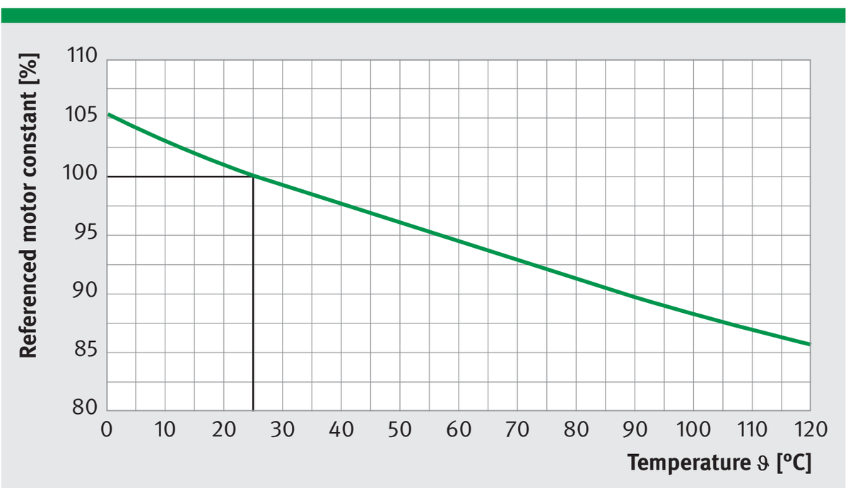
Motor constant vs. temperature
Winding resistance increases if temperature increases, which leads to a reduction of kₘ.
At a winding temperature of 100 °C the motor constant is reduced to about 0.88 times the value at 25 °C.
With a constant current or constant force, the power loss generated in a warm motor is therefore higher than that of a cold motor, and this in turn increases the motor temperature even further.
The temperature-dependent motor constant kₘ with the unit N/√W expresses the relationship between force and power loss. For further information about the dependencies between power loss and force and motor constants refer to page 7, “General Motor Parameters”.
72
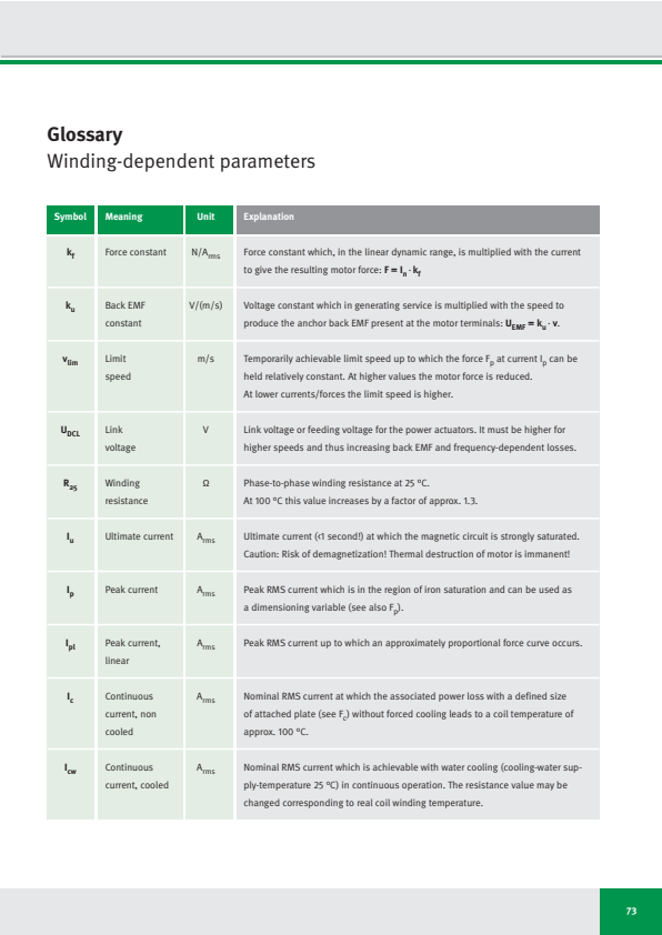
Glossary
Winding-dependent parameters
| Symbol | Meaning | Unit | Explanation |
|---|---|---|---|
| kf | Force constant | N/Arms | Force constant which, in the linear dynamic range, is multiplied with the current to give the resulting motor force: F = In · kf |
| ku | Back EMF constant | V/(m/s) | Voltage constant which in generating service is multiplied with the speed to produce the anchor back EMF present at the motor terminals: UEMF = ku · v. |
| vlim | Limit speed | m/s | Temporarily achievable limit speed up to which the force Fp at current Ip can be held relatively constant. At higher values the motor force is reduced. At lower currents/forces the limit speed is higher. |
| UDCL | Link voltage | V | Link voltage or feeding voltage for the power actuators. It must be higher for higher speeds and thus increasing back EMF and frequency-dependent losses. |
| R25 | Winding resistance | Ω | Phase-to-phase winding resistance at 25 °C. At 100 °C this value increases by a factor of approx. 1.3. |
| Iu | Ultimate current | Arms | Ultimate current (<1 second!) at which the magnetic circuit is strongly saturated. Caution: Risk of demagnetization! Thermal destruction of motor is immanent! |
| Ip | Peak current | Arms | Peak RMS current which is in the region of iron saturation and can be used as a dimensioning variable (see also Fp). |
| Ipl | Peak current, linear | Arms | Peak RMS current up to which an approximately proportional force curve occurs. |
| Ic | Continuous current, non cooled | Arms | Nominal RMS current at which the associated power loss with a defined size of attached plate (see Fc) without forced cooling leads to a coil temperature of approx. 100 °C. |
| Icw | Continuous current, cooled | Arms | Nominal RMS current which is achievable with water cooling (cooling-water supply-temperature 25 °C) in continuous operation. The resistance value may be changed corresponding to real coil winding temperature. |
73
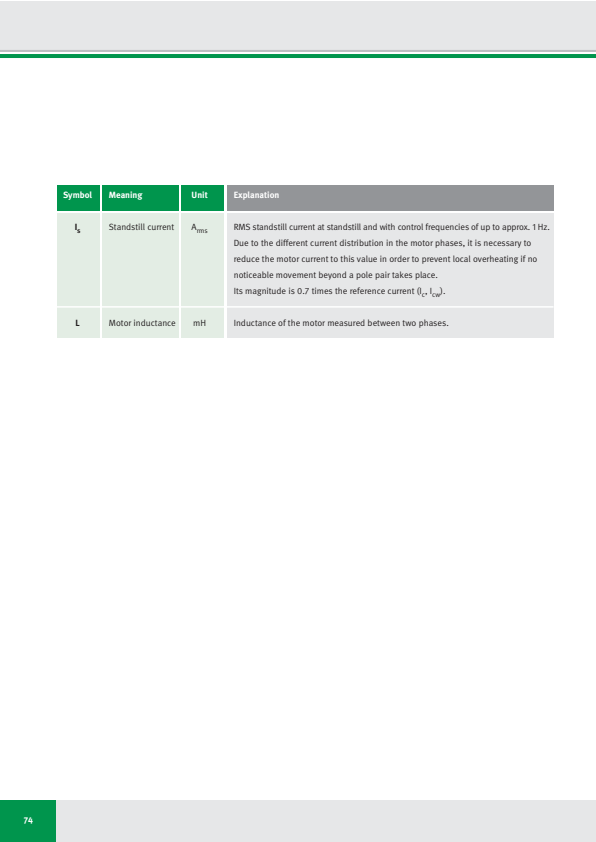
| Symbol | Meaning | Unit | Explanation |
|---|---|---|---|
| Is | Standstill current | Arms | RMS standstill current at standstill and with control frequencies of up to approx. 1 Hz. Due to the different current distribution in the motor phases, it is necessary to reduce the motor current to this value in order to prevent local overheating if no noticeable movement beyond a pole pair takes place. Its magnitude is 0.7 times the reference current (Ic, Icw). |
| L | Motor inductance | mH | Inductance of the motor measured between two phases. |
74
At a Glance: IDAM Brochures
Are you interested in more detailed technical information?
Then don't hesitate to contact us: [email protected]
LDDM
Linear motors: L1
LDDM
Linear motors: L2U
LDDM
Linear motors: ULIM
LDDM
Linear motors: FSM

RDDM
Rotary direct drive
motors
RDDS
Rotary direct drive
systems

Planar reluctance
motors
Image brochure: Direct
Drive Technology
All information about our motors and systems you can download on IDAM website: www.idam.de
75
LDDM LDDM LDDM LDDM
Linear motors: L1 Linear motors: L2U Linear motors: ULIM Linear motors: FSM
RDDM RDDS Planar reluctance Image brochure: Direct
Rotary direct drive motors Rotary direct drive systems motors Drive Technology
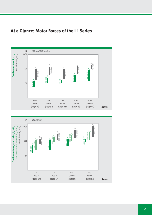
At a Glance: Motor Forces of the L1 Series
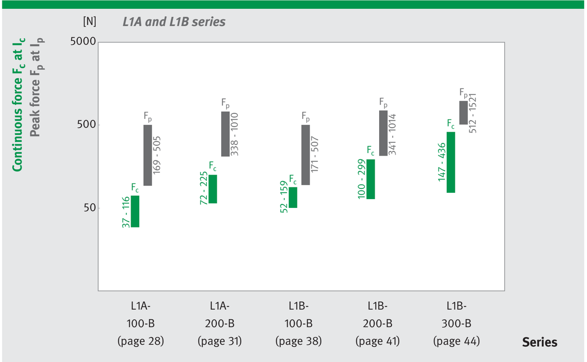
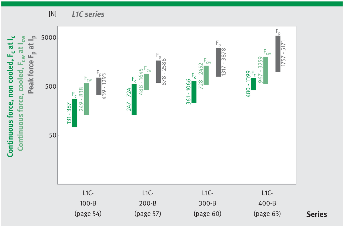
76
⚠️ Another layout reading thinks this page has no table. We still deliver what was extracted (withholding data is harder to audit than delivering it), but please look at this one on the original page yourself — per-cell confidence says whether a value has a second reading, not whether this is really a table.
この表はこのページから抽出されましたが、正確な位置を特定できなかったため、ここ(末尾)に表示しています。
⚠️ Only the vision reader saw this table — no other source overlaps it, so it may not be a real table.
| [N] | L1A and L1B series | ||||||
|---|---|---|---|---|---|---|---|
| Continous force F_c at I_c Peak force F_p at I_p | 5000 | ||||||
| F_p 169 - 505 | F_p 338 - 1010 | F_p 171 - 507 | F_p 341 - 1014 | F_p 512 - 1521 | |||
| 500 | |||||||
| F_c 37 - 116 | F_c 72 - 225 | F_c 52 - 159 | F_c 100 - 299 | F_c 147 - 436 | |||
| 50 | |||||||
| L1A- | L1A- | L1B- | L1B- | L1B- | Series | ||
| 100-B | 200-B | 100-B | 200-B | 300-B | |||
| (page 28) | (page 31) | (page 38) | (page 41) | (page 44) | |||
⚠️ Another layout reading thinks this page has no table. We still deliver what was extracted (withholding data is harder to audit than delivering it), but please look at this one on the original page yourself — per-cell confidence says whether a value has a second reading, not whether this is really a table.
この表はこのページから抽出されましたが、正確な位置を特定できなかったため、ここ(末尾)に表示しています。
⚠️ Only the vision reader saw this table — no other source overlaps it, so it may not be a real table.
| [N] | L1C series | |||||
|---|---|---|---|---|---|---|
| Continuous force, non cooled, F_c at I_c Continuous force, cooled, F_cw at I_cw Peak force F_p at I_p | 5000 | |||||
| F_p 439 - 1293 | F_p 878 - 2586 | F_p 1317 - 3878 | F_p 1757 - 5171 | |||
| 500 | ||||||
| F_cw 249 - 838 | F_cw 488 - 1645 | F_cw 728 - 2452 | F_cw 967 - 3259 | |||
| F_c 131 - 387 | F_c 247 - 724 | F_c 361 - 1066 | F_c 480 - 1399 | |||
| 50 | ||||||
| L1C- | L1C- | L1C- | L1C- | Series | ||
| 100-B | 200-B | 300-B | 400-B | |||
| (page 54) | (page 57) | (page 60) | (page 63) | |||
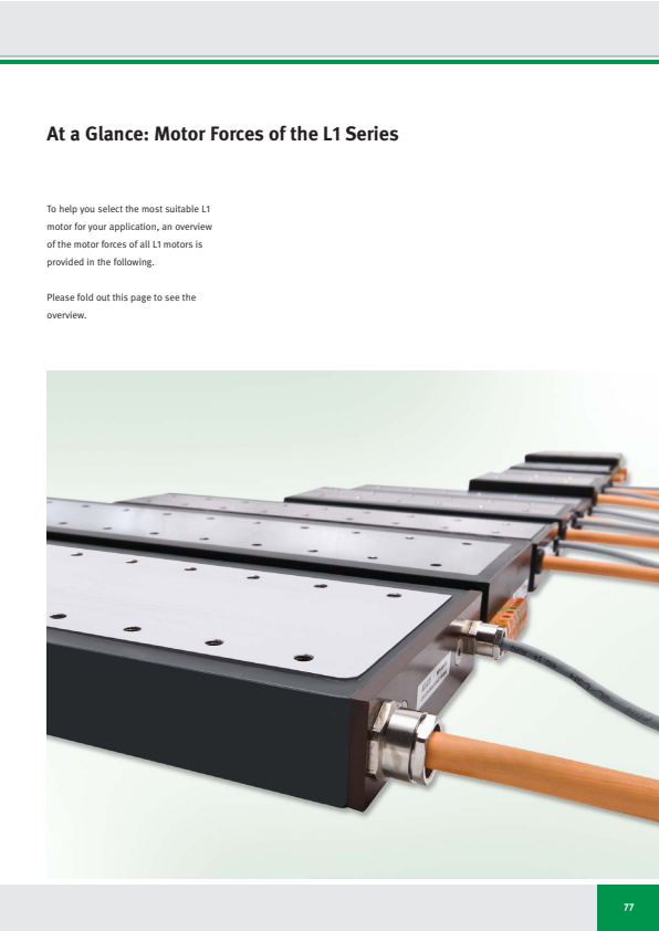
At a Glance: Motor Forces of the L1 Series
To help you select the most suitable L1 motor for your application, an overview of the motor forces of all L1 motors is provided in the following.
Please fold out this page to see the overview.
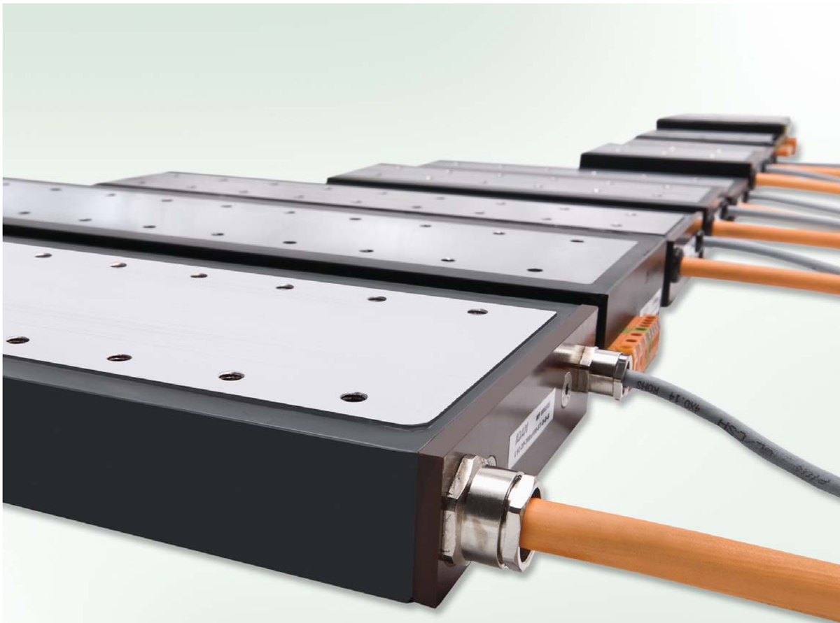
77

INA - Drives & Mechatronics GmbH & Co. oHG
Mittelbergstrasse 2
98527 Suhl | Germany
Phone +49 3681 | 7574-0
Fax +49 3681 | 7574-30
E-mail [email protected]
Web www.idam.de
Issue: January 2011 | Subject to modification without previous notice. | Photos: IDAM GmbH & Co. oHG